Dewatering and drainage construction process for inclined shaft of extra-long water-rich karst tunnel
A construction technology and inclined shaft technology, applied in drainage, safety devices, mining equipment, etc., can solve problems such as poor economy, sudden water gushing in the cavity, and high risk, so as to reduce equipment costs and operating costs, and the difficulty of installation and construction is small. The effect of high drainage efficiency
- Summary
- Abstract
- Description
- Claims
- Application Information
AI Technical Summary
Problems solved by technology
Method used
Image

Examples
Embodiment Construction
[0045] In order to make the technical problems, technical solutions and beneficial effects to be solved by the present invention clearer, the present invention will be further described in detail below in conjunction with the accompanying drawings and embodiments. It should be understood that the specific embodiments described here are only used to explain the present invention, not to limit the present invention.
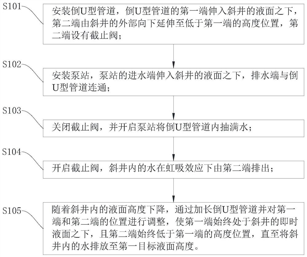
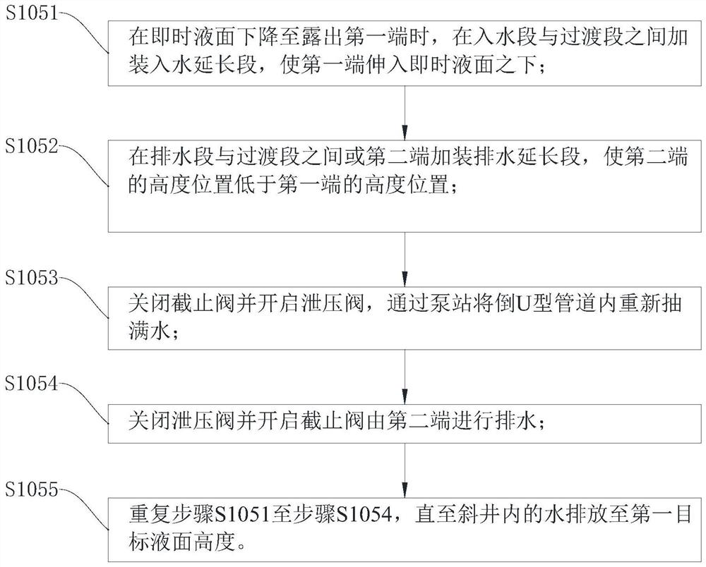
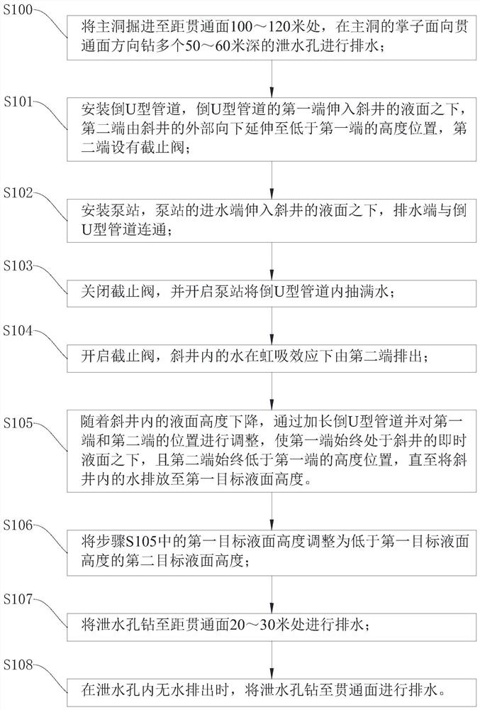
[0046] Please also refer to figure 1 , Figure 5 and Figure 7 , the construction technology for dewatering and dewatering of the inclined shaft of the super-long water-rich karst tunnel provided by the present invention will now be described. The construction technology of dewatering and drainage of the inclined shaft of the super-long water-rich karst tunnel includes the following steps:
[0047] Step S101, install the inverted U-shaped pipeline 1, the first end 110 of the inverted U-shaped pipeline 1 extends below the liquid level of the inclined well 3, and ...
PUM
 Abstract
Description
Claims
Application Information
 - Generate Ideas
- Intellectual Property
- Life Sciences
- Materials
- Tech Scout
- Unparalleled Data Quality
- Higher Quality Content
- 60% Fewer Hallucinations
Browse by: Latest US Patents, China's latest patents, Technical Efficacy Thesaurus, Application Domain, Technology Topic, Popular Technical Reports.
© 2025 PatSnap. All rights reserved.Legal|Privacy policy|Modern Slavery Act Transparency Statement|Sitemap|About US| Contact US: help@patsnap.com