Method for realizing interconnection between microwave signal boards and interconnected microwave signal board

A technology of microwave signal and signal board, applied in the field of active phased array, can solve the problems of reliability and inability to meet the elastic expansion and contraction, and achieve the effect of compact structure

Active Publication Date: 2022-02-11
SOUTHWEST CHINA RES INST OF ELECTRONICS EQUIP
View PDF6 Cites 0 Cited by
  • Summary
  • Abstract
  • Description
  • Claims
  • Application Information

AI Technical Summary

Problems solved by technology

The advantage of this method is that the frequency of signal transmission is high and the vibration resistance is large, but it also has three disadvantages: the relative distance between the upper composite substrate and the lower composite substrate exceeds 10mm, and multiple sets of fur buttons are required to be connected in series to achieve long-distance transmission. , there are reliability problems; the protruding length of the fur button thimble is related to the compression of the fur button, generally within 10% (the maximum stretching length of the thimble is 0.5mm), which cannot meet the demand for greater elastic expansion; the fur button is integrated in the metal frame In the medium body, if there are too many fur buttons integrated in a frame, some or some of the fur buttons are damaged, and the entire frame needs to be removed for repair and replacement

Method used


Image

  • Method for realizing interconnection between microwave signal boards and interconnected microwave signal board
  • Method for realizing interconnection between microwave signal boards and interconnected microwave signal board
  • Method for realizing interconnection between microwave signal boards and interconnected microwave signal board

Examples


Embodiment 1

[0039] There are following technical problems in the prior art:

[0040] 1. Long-distance signal vertical transmission and external vertical interconnection between boards of microwave signals;

[0041] 2. The problem of low torque plugging and unplugging of composite substrates;

[0042] 3. Disassembly and maintenance of the elastic mechanism;

[0043] 4. The problem of signal interconnection between composite substrates with excessive warpage.

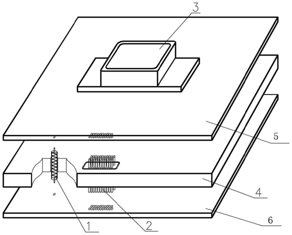
[0044] In order to solve the above technical problems, this embodiment provides a method for interconnecting microwave signal boards, which specifically includes the following contents:

[0045] In this example, if figure 1 As shown, taking the adjacent composite substrate 1 and composite substrate 2 as an example, firstly, an interlayer adapter plate for supporting the composite substrate is arranged in the middle of the adjacent composite substrate 1 and composite substrate 2, and in the A limit hole for the limit spring connec...


PUM


Abstract

The invention relates to the field of active phased arrays, and discloses a method for realizing interconnection between microwave signal boards and an interconnected microwave signal board. The interlayer adapter board is provided with a limit hole for limiting the spring connection structure; a separable spring connection structure is arranged between the adjacent upper and lower composite substrates to connect all the The spring connection structure is arranged in the limit hole, and metal pads are arranged at the positions of the adjacent upper and lower composite substrates corresponding to the spring connection structure; the adjacent upper and lower composite substrates are squeezed, and the The spring connection structure is in contact with the metal pads on the upper and lower composite substrates to realize interconnection; after the interconnection is completed, a high and low frequency mixed joint assembly for external connection is arranged on the upper composite substrate. The present invention can realize the vertical interconnection between boards of more than 10 mm, and has high expansibility.

Description

technical field [0001] The invention relates to the field of active phased arrays, in particular to a method for realizing interconnection between microwave signal boards and an interconnected microwave signal board. Background technique [0002] There are many methods for inter-board interconnection of microwave signals, and there are mainly two traditional methods: [0003] The first is to use the RF connector SMP or SMPM plus a transition adapter KK to realize the transition between the composite substrate 1 and the composite substrate 2. The disadvantage of this method is that there is an insertion between the transition adapter KK and the RF connector SMPM. Pulling torque, when more than 100 sets of connection structures are plugged and pulled between the boards at the same time, there will be a large torque, which will make it difficult to pull out and insert, and the composite substrate will be twisted and deformed, and even damage the devices carried on the substrate...

Claims


Application Information

Patent Timeline
Patent Type & Authority Patents(China)
IPC IPC(8): H01P3/02H01P5/08
CPCH01P3/02H01P5/08
Inventor 杨非蔡雪芳王欢周俊笪余生高阳廖翱彭文超丁浩周平
Owner SOUTHWEST CHINA RES INST OF ELECTRONICS EQUIP
Why Eureka
Try Eureka