Fault isolation system and method

A fault isolation and sub-system technology, applied in the direction of electrical components, emergency protection circuit devices, etc., can solve the problems of expanded fault range and high cost, and achieve the effects of low-cost fault isolation, improved reliability, and reduced voltage

Pending Publication Date: 2021-10-08
CHINA ELECTRIC POWER RES INST +1
View PDF0 Cites 0 Cited by
  • Summary
  • Abstract
  • Description
  • Claims
  • Application Information

AI Technical Summary

Problems solved by technology

[0004] In order to overcome the disadvantages of high cost and easy expansion of the fault range in the above-mentioned prior art, the present invention provides a fault isolation system, including a primary system and a secondary system, the secondary system is coupled with the primary system; the primary The input end of the system is connected to the new energy system through the positive DC bus and the negative DC bus, and the output end of the primary system is connected to the public DC grid;

Method used


Image

  • Fault isolation system and method
  • Fault isolation system and method
  • Fault isolation system and method

Examples


Embodiment 1

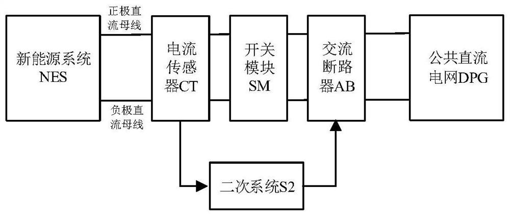
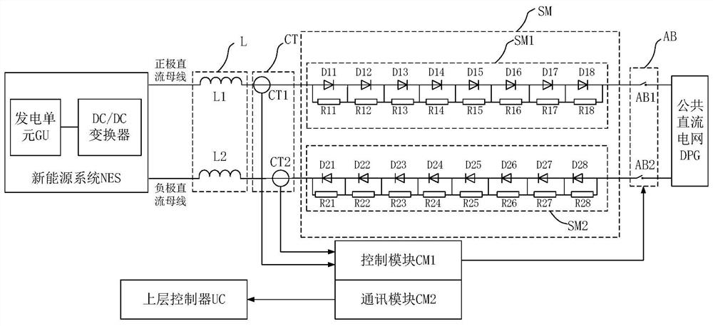
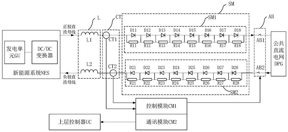
[0046] Embodiment 1 of the present invention provides a fault isolation system, such as figure 1 As shown, the fault isolation system S includes a primary system S1 and a secondary system S2, and the secondary system S2 is coupled with the primary system S1; the input of the primary system S1 is connected to the new energy system NES (such as figure 2 As shown, the new energy system NES includes the power generation unit GU and the DC / DC converter) connection, and the output terminal of the primary system S1 is connected to the public DC power grid DPG;

[0047] The primary system S1 includes a current sensor CT, a switch module SM and an AC circuit breaker AB connected in series on the positive DC bus and the negative DC bus in sequence;

[0048]The current sensor CT is used for: collecting the current analog signal flowing through the positive DC bus and the negative DC bus. understandable, such as figure 2 As shown, the current sensor CT includes a current sensor CT1 an...

Embodiment 2

[0072] Embodiment 2 of the present invention provides a fault isolation method, such as Figure 4 As shown, the specific process is as follows:

[0073] S101: Use the current sensor in the primary system to collect the current analog signal flowing through the positive DC bus and the negative DC bus; the positive DC bus and the negative DC bus are coupled to the new energy system and the public DC grid;

[0074] S102: When the positive DC bus and / or the negative DC bus fail, use the switch module in the primary system to block the unidirectional flow of current;

[0075] S103: Based on the current analog signal from the current sensor, use the secondary system to judge whether the positive DC bus and / or the negative DC bus is faulty, and control the AC in the primary system when the positive DC bus and / or the negative DC bus are faulty The circuit breaker opens.

[0076] In the above S103, based on the current analog signal from the current sensor, use the secondary system t...


PUM


Abstract

The invention provides a fault isolation system and method. The system comprises a primary system and a secondary system, and the secondary system is coupled with the primary system. The input end of the primary system is connected with the new energy system through a positive direct-current bus and a negative direct-current bus, and the output end of the primary system is connected with the public direct-current power grid; and the primary system comprises a current sensor, a switch module and an alternating current circuit breaker which are sequentially connected in series on the positive pole direct current bus and the negative pole direct current bus. According to the invention, the alternating-current circuit breaker and the switch module are connected in series, so that physical switching-on and switching-off of the new energy system and the public direct-current power grid are realized, that is, isolation of the new energy system and the public direct-current power grid is realized, and low-cost fault isolation is realized on the premise of ensuring the opening speed of the alternating-current circuit breaker.

Description

technical field [0001] The invention relates to the technical field of DC power grids, in particular to a fault isolation system and method. Background technique [0002] In recent years, public DC power grids have been widely used, and new energy systems and loads are also increasing. The power generation unit of the new energy system mainly includes photovoltaic power generation and wind power generation. The new energy system is connected to the public DC grid through a DC converter. The power generation unit needs to be equipped with a fault isolation device when it is connected to the grid. Its function is to ensure that the new energy system can be physically disconnected from the public DC grid when a fault occurs inside the new energy system, and at the same time ensure that the internal fault of the new energy system does not affect the safe and stable operation of the public DC grid. . [0003] At present, most DC circuit breakers are usually used as the fault i...

Claims


Application Information

Patent Timeline
Patent Type & Authority Applications(China)
IPC IPC(8): H02H7/22H02H7/26
CPCH02H7/22H02H7/268
Inventor 刘纯李洋何国庆
Owner CHINA ELECTRIC POWER RES INST
Why Eureka
Try Eureka