Trip device and spring operating mechanism using the trip device

A technology of tripping device and operating mechanism, which is applied in the direction of contact operating mechanism, power device inside the switch, contact vibration/shock damping, etc., and can solve the problem of damage to the moving contact, failure of tripping, and affecting the initial speed of opening and other problems, to achieve the effect of simple structure and low production cost

Active Publication Date: 2017-01-18
PINGGAO GRP +1
View PDF5 Cites 0 Cited by
  • Summary
  • Abstract
  • Description
  • Claims
  • Application Information

AI Technical Summary

Problems solved by technology

The problem with this existing tripping device is that the tripping shaft is fixed on the lock bolt, and the tripping shaft cannot rotate. When the tripping fitting presses the tripping shaft, the tripping shaft cannot rotate and cooperate with the tripping There is completely sliding friction between the tripping shaft and the tripping fitting. Excessive friction between the tripping shaft and the tripping fitting is likely to cause tripping failure. In addition, the movement track of the tripping shaft is centered on the hinge axis of the lock bolt. The arc movement causes the tripping shaft to fail to disengage from the tripping fitting as soon as possible during the opening process, which will affect the initial opening speed of the dynamic and static contacts
In addition, the buffer in the existing spring operating mechanism also has the following problems: 1. The buffer has the same damping effect on the output shaft during opening and closing, which does not meet the actual needs of the spring operating mechanism. Because in actual work, the impact of the buffer on the closing process is as small as possible. The closing force of the closing spring is expected to be completely transmitted to the moving contact instead of being absorbed by the buffer. The buffer is more important to the closing process. Absorption of opening force; 2. The buffer has a damping effect on the output shaft at the beginning of closing and opening of the dynamic and static contacts, which will affect the initial speed of closing and opening of the dynamic and static contacts , the moving contacts are vulnerable to arc damage

Method used


Image

  • Trip device and spring operating mechanism using the trip device
  • Trip device and spring operating mechanism using the trip device
  • Trip device and spring operating mechanism using the trip device

Examples


Embodiment Construction

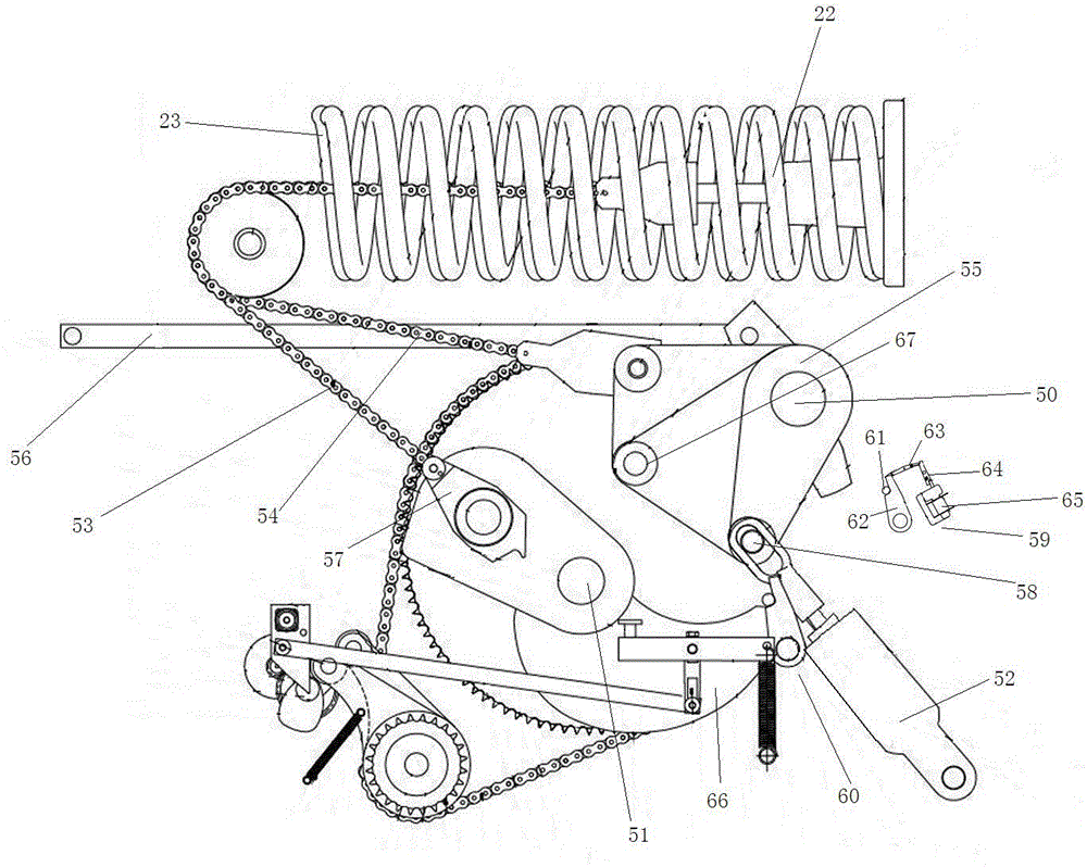
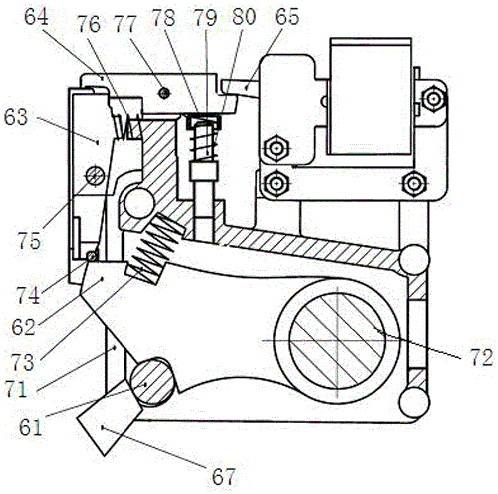
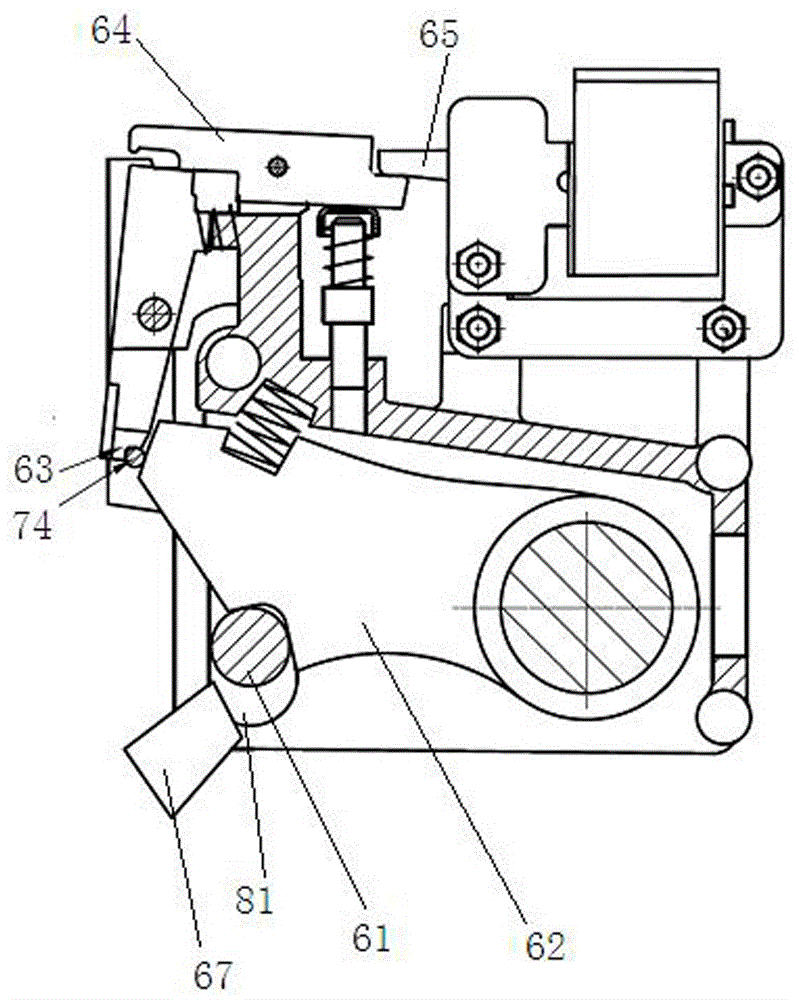
[0033] Examples of spring-operated mechanisms are Figure 1~14 Shown: including a frame, the frame is provided with an energy storage spring buffer 52 and an output shaft 50 and an energy storage shaft 51 whose axis extends in the left and right directions. The energy storage spring is divided into an opening spring 23, a closing spring 22, an energy storage The shaft is provided with the energy storage shaft cam and the energy storage detent 57 connected with the closing spring by the closing spring chain 53, and the energy storage shaft sprocket is also arranged on the energy storage shaft, and the closing and release mechanism is arranged on the energy storage shaft sprocket. Buckle fittings, a closing and tripping device 60 is arranged next to the energy storage shaft, and the spring operating mechanism also includes a motor that is connected to the sprocket of the energy storage shaft through a transmission mechanism. The switch arm 55, the buffer lever is an integrated l...


PUM


Abstract

Disclosed are a tripping device and a spring operated mechanism using same. The tripping device comprises a device rack (71) and a first tripping shaft (61), wherein a first lock plunger (62) of which the hinging axis extends in a left-right direction is hinged to the device rack; a first reset spring (73) is provided between the first lock plunger and the device rack; an unlocking mechanism fitted to the first lock plunger is also provided on the device rack; a first guide groove (81) of which the guide direction extends in an up-down direction is provided on the device rack; the first tripping shaft is assembled in the first guide groove in guided motion, and the first tripping shaft is rotationally fitted to the first guide groove; and the first lock plunger is provided with a first tripping shaft pushing fitting part which forms a pushing fit with the first tripping shaft so as to push the first tripping shaft to an energy storage holding position under the action of the first reset spring. The first tripping shaft makes a linear motion along the first guide groove in the tripping process, thereby increasing the tripping speed. Moreover, when a tripping fitting piece presses the first tripping shaft, rolling friction exists therebetween, thereby ensuring tripping reliability.

Description

technical field [0001] The invention relates to a tripping device and a spring operating mechanism using the tripping device. Background technique [0002] The spring operating mechanism generally includes a frame, a closing spring, an opening spring, and an energy storage shaft and an output shaft arranged in parallel on the frame. The energy storage shaft is connected to the closing spring through a closing spring chain, and the output shaft The opening spring chain is connected with the opening spring transmission, the energy storage shaft is provided with a closing detent, the output shaft is connected with a buffer and a tripping fitting through a crank arm, and a closing detent is provided beside the energy storage shaft. The closing and tripping device matched with the sub, and the opening and tripping device matched with the tripping fitting is arranged next to the output shaft. When the energy storage of the closing spring is required, the motor drives the energy s...

Claims


Application Information

Patent Timeline
Patent Type & Authority Patents(China)
IPC IPC(8): H01H3/30H01H3/60
CPCH01H3/30H01H3/54
Inventor 宋超闫光超刘宇朱苛娄郭良超宋广民王守山许家源苏计东钟建英
Owner PINGGAO GRP
Why Eureka
Try Eureka