High-pressure cleaning machine for microscope lens

A technology for high-pressure cleaners and microscope lenses, applied in cleaning methods and utensils, cleaning methods using gas flow, chemical instruments and methods, etc. The effect of liberating manpower, reasonable structure and improving cleaning efficiency

Active Publication Date: 2021-10-12
望江县天长光学仪器有限公司
View PDF15 Cites 0 Cited by
  • Summary
  • Abstract
  • Description
  • Claims
  • Application Information

AI Technical Summary

Problems solved by technology

[0005] The purpose of the present invention is to provide a high-pressure cleaning machine for microscope lenses to solve the problem that the existing high-pressure cleaning equipment for lenses proposed in the background technology above needs to manually turn over the lens when cleaning the lens, and adjust the position of the lens to realize double-sided cleaning of the lens. Cleaning is easy to stain the lens, the cleaning efficiency is low, and it is inconvenient to take and place, which cannot liberate manpower

Method used


Image

  • High-pressure cleaning machine for microscope lens
  • High-pressure cleaning machine for microscope lens
  • High-pressure cleaning machine for microscope lens

Examples


specific Embodiment approach 1

[0029] Specific implementation mode one: please refer to Figure 1-6 , the present invention provides a technical solution: a high-pressure cleaning machine for microscope slides, comprising:

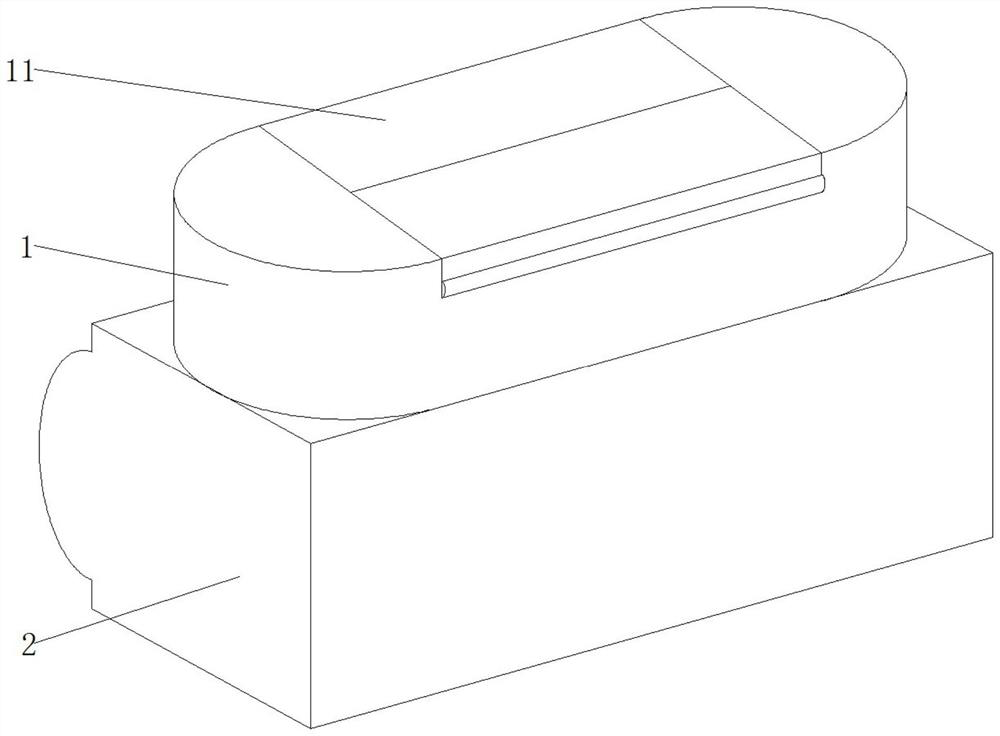
[0030] The upper layer 1 and the lower layer 2 are stacked up and down and connected together, and the upper layer 1 is connected to the lower layer 2 through the communication groove 14; the front sides of the upper layer 1 and the lower layer 2 can be made of transparent material, which is convenient for observing the lens cleaning progress.

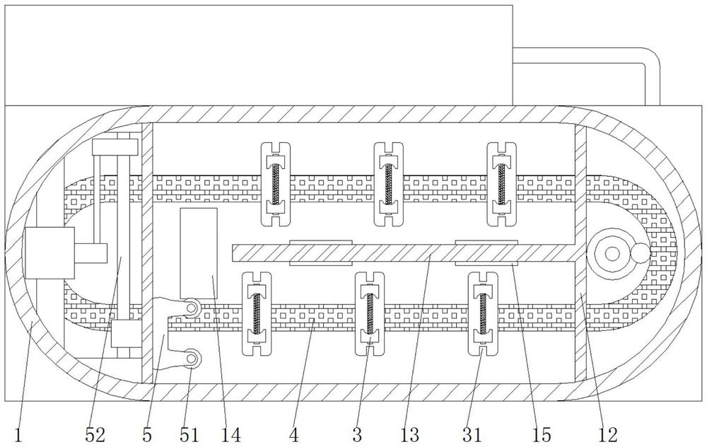
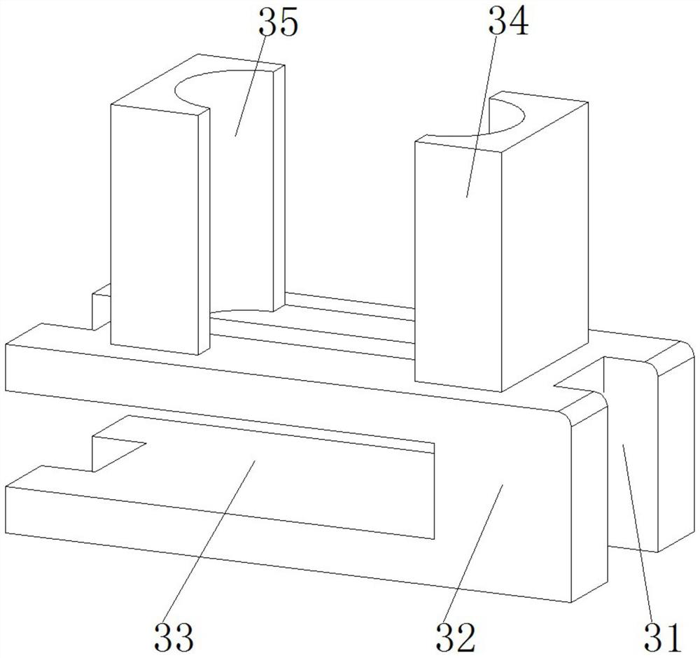
[0031] The clamping mechanism 3 is clamped on the transmission belt 4. The clamping mechanism 3 includes a base 32 and a clamping block 34 installed on the top surface of the base 32. The transmission belt 4 is a circular conveying structure, with one side input and one side output.

[0032] The sliding plate 5 is used to adjust the horizontal position of the clamping mechanism 3. One end of the sliding plate 5 passes through the first partition...

specific Embodiment approach 2

[0037] Specific embodiment two: this embodiment is a further limitation of specific embodiment one, such as figure 1 and figure 2 As shown, the upper layer 1 is in the shape of a rectangular box with rounded corners, an upper cover 11 is installed in the middle of the top surface of the upper layer 1, a first partition plate 12 and a second partition plate 13 are fixed inside the upper layer 1, and a connecting plate is opened on the bottom plate of the upper layer 1. Groove 14, fan 15 is embedded on the second partition 13, with the second partition 13 as the dividing line, the two sides of the second partition 13 are respectively the discharge side and the discharge side, and the two loam cakes 11 are covered separately. On the discharge side and the discharge side, the upper and lower materials do not interfere with each other, and the fan 15 is used to dry the cleaned lenses.

specific Embodiment approach 3

[0038] Specific implementation mode three: this implementation mode is a further limitation of specific implementation mode two, such as figure 2 As shown, the first partition 12 and the rounded corner near the first partition 12 form a semicircular groove, and a sliding mechanism 52 is installed in the semicircular groove formed by the first partition 12 on the left side, and the second partition 13 is located at On the line connecting the centers of the two semicircles, the length of the second partition 13 is less than the distance between the first partitions 12, the second partition 13 is connected to the first partition 12 on the right side, and the communication groove 14 is located at the first partition on the left side. Between the partition 12 and the second partition 13, a sliding mechanism 52 and a driving mechanism of the transmission belt 4 are installed in the semicircular groove, which cooperate with the top plate of the upper layer 1 to form a closed mechanis...


PUM


Abstract

The invention discloses a high-pressure cleaning machine for a microscope lens. The high-pressure cleaning machine comprises an upper layer, a lower layer, a clamping mechanism, a sliding plate, a high-pressure airflow generator and a jacking mechanism, wherein the upper layer and the lower layer are connected together in an up-down stacked mode, and the upper layer communicates with the lower layer through a communicating groove; the clamping mechanism is clamped on a transmission belt, and the clamping mechanism comprises a base and a clamping block mounted on the top surface of the base; the sliding plate is used for adjusting the horizontal position of the clamping mechanism; the high-pressure airflow generator is mounted on the rear side of the lower layer, and the high-pressure airflow generator is connected with a flushing nozzle; and the jacking mechanism is used for adjusting the vertical position of the clamping mechanism, and the jacking mechanism comprises a jacking air cylinder, a motor and a second electromagnetic block. According to the high-pressure cleaning machine for the microscope lens, the clamping mechanism is rotated through the jacking mechanism, an automatic overturning function for the lens is achieved, manual operation is replaced, the cleaning efficiency is improved, meanwhile, the opening direction of a U-shaped base of the clamping mechanism is changed before and after overturning, the sliding plate and the circulating transmission belt are combined, automatic feeding and discharging are avoided, use is convenient, and manpower is saved.

Description

technical field [0001] The invention relates to the related technical field of cleaning equipment, in particular to a high-pressure cleaning machine for microscope sheets. Background technique [0002] A microscope is an optical instrument composed of a lens or a combination of several lenses. It is a sign that human beings have entered the atomic age. The microscope needs regular maintenance and cleaning. If the stains on the lens are not cleaned in time, it will affect the use. [0003] However, the microscope lens cannot be wiped arbitrarily, otherwise it will scratch the lens. The existing lens high-pressure cleaning equipment needs to manually turn over the lens when cleaning the lens, and adjust the position of the lens, so as to realize double-sided cleaning of the lens, which is easy to deface the lens. Efficiency is low, and the prior art needs to take out the upper lens before putting in the lower lens when cleaning, which is not convenient enough and cannot libera...

Claims


Application Information

Patent Timeline
Patent Type & Authority Applications(China)
IPC IPC(8): B08B5/02B08B13/00
CPCB08B5/023B08B13/00
Inventor 孙金华
Owner 望江县天长光学仪器有限公司
Why Eureka
Try Eureka