
Auxiliary calibration mechanism for special-shaped steel processing

A calibration mechanism and special-shaped steel technology, applied in metal processing, metal processing equipment, manufacturing tools, etc., can solve problems such as insufficient calibration, and achieve the effect of improving stability and convenient and rapid replacement.

Active Publication Date: 2022-04-05
江苏华杰不锈钢制品有限公司
View PDF13 Cites 0 Cited by
  • Summary
  • Abstract
  • Description
  • Claims
  • Application Information

AI Technical Summary

Problems solved by technology

[0003] Referring to the publication number: CN108673058B shows the straight seam welded special-shaped steel pipe forming process and mold replacement device for the automobile anti-collision beam. This invention specifically points out the straight seam welded special-shaped steel pipe for the automobile anti-collision beam. The problem of mold replacement during the processing of beam straight seam welded special-shaped steel pipes is still insufficient in the calibration of straight seam welded special-shaped steel pipes for automobile beams

Method used


Image

  • Auxiliary calibration mechanism for special-shaped steel processing
  • Auxiliary calibration mechanism for special-shaped steel processing
  • Auxiliary calibration mechanism for special-shaped steel processing

Examples


Embodiment 1

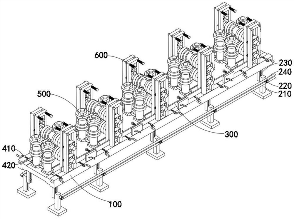
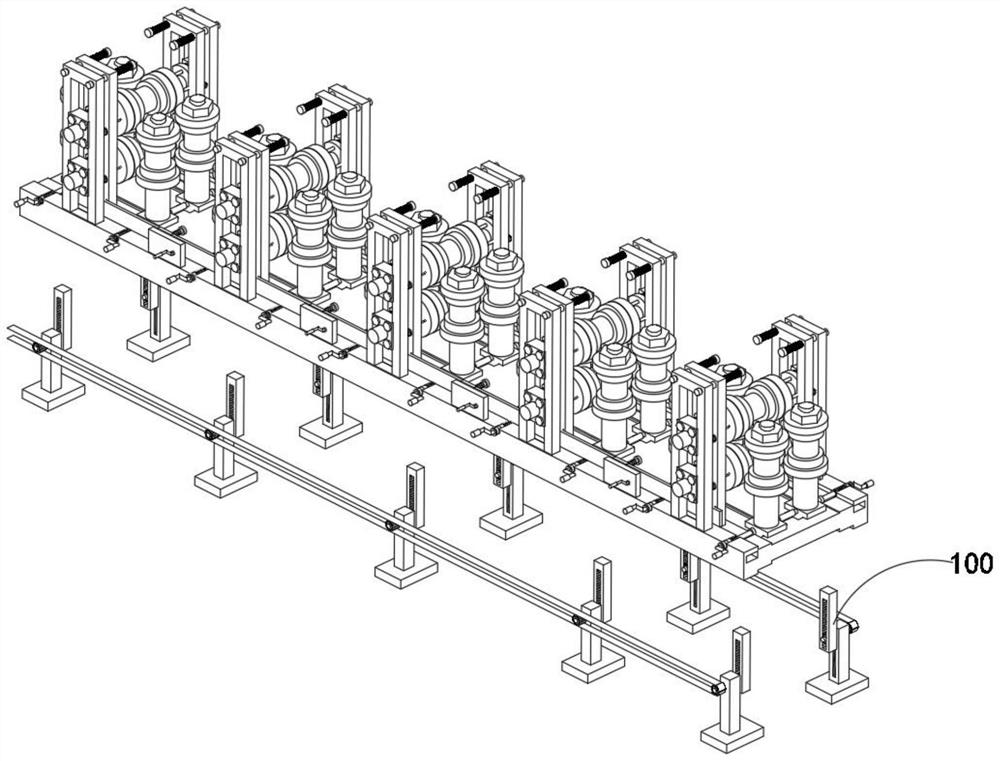
[0056] combine figure 1 , 4 , 6, 9, 10 and 12, the auxiliary calibration mechanism for special-shaped steel processing provided by the present invention includes a support mechanism 100, a lifting mechanism 200, a propulsion mechanism 300, a fine-tuning assembly 400, a vertical restraint mechanism 500 and a special-shaped steel calibration mechanism 600, wherein the lifting mechanism 200 is installed on the support mechanism 100, and the propulsion mechanism 300 is movably installed on the support mechanism 100, the fine-tuning assembly 400 is welded in the support mechanism 100, in addition, the vertical constraint mechanism 500 is movably installed in the support mechanism 100 In the chute, the special-shaped steel calibration mechanism 600 is fixedly installed on the support mechanism 100 .

[0057] The support mechanism 100 includes a working surface 110 and a riser 120, the lifting mechanism 200 includes a base 210, a shaft rod 220, a leg 230 and a chain 240, and the pro...

Embodiment 2

[0060] combine figure 1 As shown, in the above-mentioned embodiment, by fixing the riser 120 on both sides of the top of the worktable surface 110, when the rocker on the deflection toothed plate 360 ​​penetrates to the outside of the riser 120, it is constrained by the support of the riser 120, At this time, the deflection toothed plate 360 ​​can stably drive the external pull rod and promote the rotation of the screw rod 340. The support mechanism 100 also includes vertical plates 120 evenly installed on both sides of the top of the worktable 110, and the vertical plates 120 have built-in through holes.

Embodiment 3

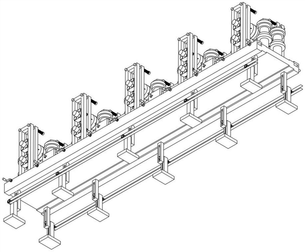
[0062] combine Figure 4 As shown, in the above-mentioned embodiment, the evenly distributed legs 230 are installed on the bottom of the work surface 110, and the base 210 is movably installed on the sliders outside the legs 230, and the shaft rod located in the inner notch of the legs 230 is used to The rotation of 220 drives the lifting and lowering of the supporting leg 230. At this time, the working table 110 of the device can quickly be in a horizontal parallel state with the existing machine tool. The lifting mechanism 200 includes the supporting leg 230 installed at the bottom of the working table The base 210 outside the legs 230 and the shaft 220 inside the base 210 and the chain 240 engaged at the outer end of the shaft 220 .


PUM


Abstract

The invention discloses an auxiliary calibration mechanism for special-shaped steel processing, including a support mechanism, a lifting mechanism, a propulsion mechanism, a fine-tuning assembly, a vertical restraint mechanism, and a special-shaped steel calibration mechanism. The support mechanism includes a working table for providing a stable work flow, The lifting mechanism is installed on the bottom of the worktable, the propulsion mechanism includes a balance part and a driving part, and the balance part includes steel slats, inner pads installed at intervals outside the steel slats and welded on the inner pads Central screw. By setting the worktable, the groove and chute on the top of the worktable are used to fit and install the passive calibration combination. When the mold needs to be replaced, the operator only needs to rotate the deflection chainring counterclockwise, so that the pull rod on the deflection chainring comes The driving screw rotates, and at this time, the screw drives the screw sleeve, thereby prompting the steel slats to drive multiple sets of inner frames to shrink inward, which greatly facilitates the rapid replacement of the mold by the operator.

Description

technical field [0001] The invention relates to the field of special-shaped steel processing, in particular to an auxiliary calibration mechanism for special-shaped steel processing. Background technique [0002] Special-shaped steel pipes are the general term for seamless steel pipes with cross-sectional shapes other than round pipes. According to the cross-sectional shape and size of steel pipes, they can be divided into special-shaped seamless steel pipes with equal wall thickness (D pipes) and special-shaped seamless steel pipes with different wall thicknesses ( BD pipe), variable diameter special-shaped seamless steel pipe (BJ pipe). [0003] Referring to the publication number: CN108673058B shows the straight seam welded special-shaped steel pipe forming process and mold replacement device for the automobile anti-collision beam. This invention specifically points out the straight seam welded special-shaped steel pipe for the automobile anti-collision beam. The problem...

Claims


Application Information

Patent Timeline
Patent Type & Authority Patents(China)
IPC IPC(8): B21C37/08B21C25/02B21C51/00
CPCB21C37/08B21C25/02B21C51/00
Inventor 许春华孙建荣韩延祥许春梅朱小芳
Owner 江苏华杰不锈钢制品有限公司
Learn More