Strip lamp assembly tool

A technology for assembling tooling and long light bars, which is applied in the direction of assembly machines, metal processing, manufacturing tools, etc., can solve problems that affect production efficiency, affect assembly efficiency, and poor applicability, so as to ensure flatness and improve assembly efficiency , to achieve the effect of automatic feeding

Active Publication Date: 2021-10-15
SELF ELECTRONICS CO LTD
View PDF21 Cites 3 Cited by
  • Summary
  • Abstract
  • Description
  • Claims
  • Application Information

AI Technical Summary

Problems solved by technology

However, this patent still cannot solve the following problems: (1) The end caps at both ends of the lamp are not installed on the same plane, and the flatness of the product cannot be effectively guaranteed; (2) The applicability is not good, and it cannot be applied to various types of LED strips The assembly of lamps, and frequent line changes in actual production will affect production efficiency; (3) Automatic screwing cannot be realized, thus affecting assembly efficiency

Method used


Image

  • Strip lamp assembly tool
  • Strip lamp assembly tool
  • Strip lamp assembly tool

Examples


Embodiment Construction

[0034] The present invention will be further described in detail below in conjunction with the accompanying drawings and embodiments.

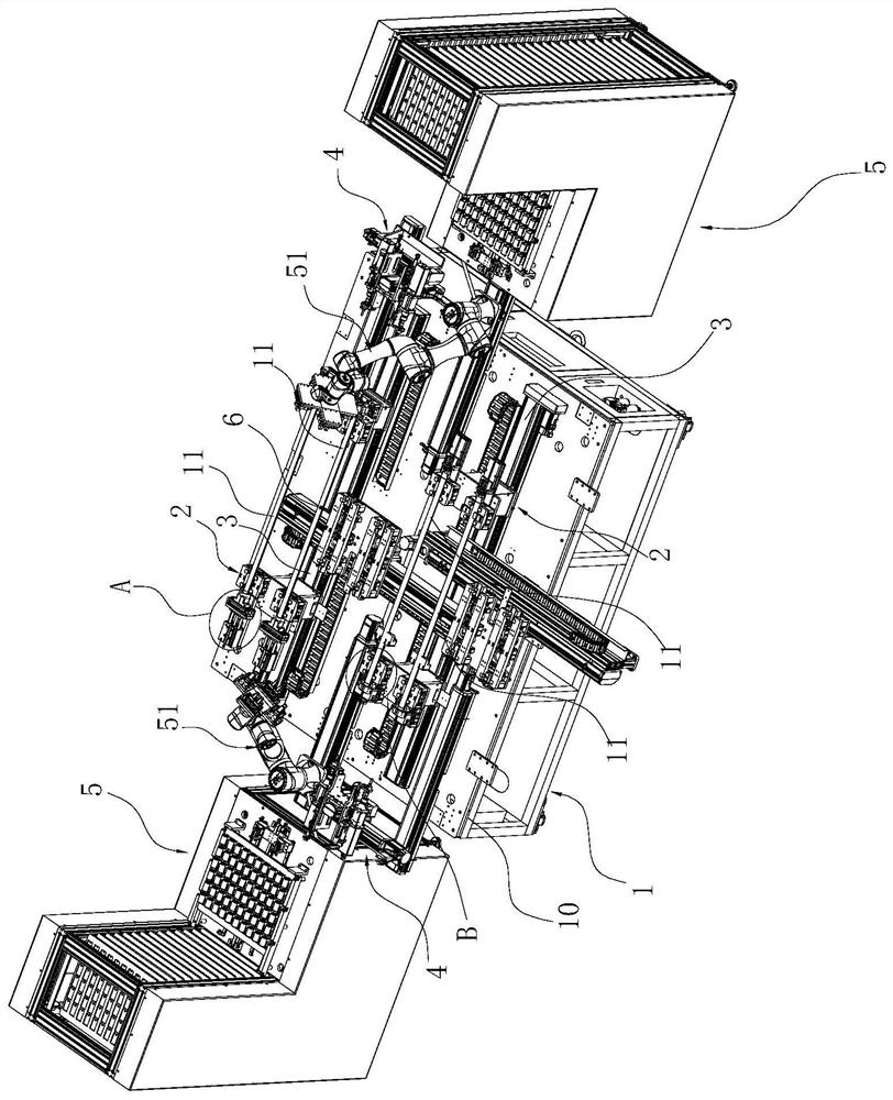
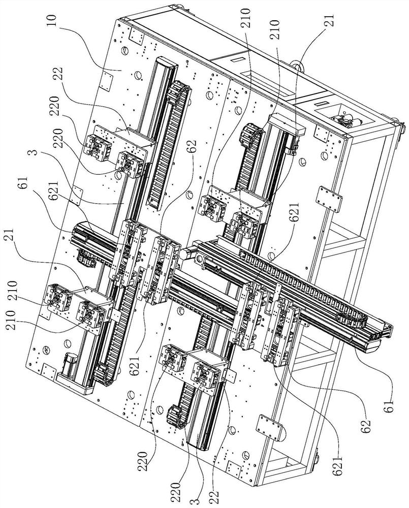
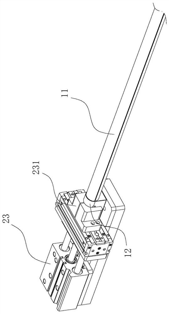
[0035] Such as Figure 1-12 As shown, a light bar assembly tooling (in this embodiment, the light bar is an LED light bar) includes a frame 1 with a workbench 10 on the top, and is characterized in that it also includes a Aluminum bottom loading mechanism 2, distance adjustment slide rail 3 and screw driving mechanism 4 on the table. Wherein, the above-mentioned aluminum bottom loading mechanism 2 includes a first sliding seat 21 for positioning the first end of the aluminum bottom 11 and a second sliding seat 22 for positioning the second end of the aluminum bottom 11, the first sliding seat 21 and the second sliding seat 22 The two sliding seats 22 are arranged opposite to each other along the left and right directions. The above-mentioned first sliding seat 21 is provided with a first push cylinder 23 for pushing the end cover 12 onto the ...


PUM


Abstract

The invention relates to a strip lamp assembly tool. The strip lamp assembly tool comprises an aluminum bottom loading mechanism, a distance adjusting sliding rail, a screw driving mechanism and an end cover feeding mechanism, loading and positioning of an aluminum bottom can be achieved through the aluminum bottom loading mechanism, a first sliding seat and a second sliding seat are arranged in the left-right direction, it is guaranteed that end covers at the two ends of the aluminum bottom are installed on the same plane, and the assembling straightness of the lamp is ensured; and meanwhile, the distance between the sliding seats of the aluminum bottom loading mechanisms can be adjusted through the distance adjusting sliding rails, so that the aluminum bottom loading mechanisms can be used for loading strip lamps of different specifications, the tool assembling machine can be suitable for assembling the strip lamps of different specifications, the screw driving mechanism can achieve automatic screw driving so that the end covers and the end of the aluminum bottom can be fixed into a whole through screws, compared with a manual screw driving mode, the assembling efficiency of the strip lamp can be greatly improved through the automatic screw driving mode, and in addition, automatic feeding of the end covers can be achieved through the end cover feeding mechanism.

Description

technical field [0001] The invention relates to the field of lamp assembly, in particular to a tooling for a strip light device. Background technique [0002] LED strip lights generally include a strip-shaped aluminum bottom and end caps installed on both ends of the aluminum bottom. The final end cover assembly is installed on both sides of the aluminum bottom, and finally the end cover is fixed on the aluminum bottom by manual screwing. The manual method has the problems of high labor intensity and low production efficiency, and the quality of assembly cannot be guaranteed. [0003] In order to solve the above problems, the Chinese utility model patent with the patent number ZL201821957658.1 (the authorized announcement number is CN 209078183 U) discloses a lamp cover assembly mechanism, specifically, the lamp cover assembly mechanism includes a frame, a feeding Mechanism, unloading mechanism and product positioning mechanism, the product positioning mechanism includes a...

Claims


Application Information

Patent Timeline
Patent Type & Authority Applications(China)
IPC IPC(8): B23P21/00
CPCB23P21/004B23P19/001B23P19/007B23P19/006Y02P70/50
Inventor 郭武陈江平万晓云李勋
Owner SELF ELECTRONICS CO LTD
Why Eureka
Try Eureka