Novel machining, positioning and overturning device for hydraulic accessories

A positioning inversion, hydraulic technology, applied in positioning devices, metal processing equipment, metal processing machinery parts, etc., can solve the problems of inconvenience, low production efficiency of hydraulic parts, inconvenient hydraulic parts turnover, etc., to improve production efficiency and improve practicability Effect

Active Publication Date: 2021-10-15
重庆君工装饰工程有限责任公司
View PDF16 Cites 0 Cited by
  • Summary
  • Abstract
  • Description
  • Claims
  • Application Information

AI Technical Summary

Problems solved by technology

[0007] The purpose of the present invention is to provide a new type of processing and positioning turning device for hydraulic fittings, to solve the problem that most of the positioning turning devices proposed in the above background technology can only position and clamp a single hydraulic fitting. When it is used, it is difficult to meet the clamping and positioning of a large number of hydraulic accessories, which leads to the low production efficiency of hydraulic accessories. Currently, a positioning device that can perform multiple clamping and positioning of hydraulic accessories at one time is not convenient for clamping and positioning hydraulic accessories. Turning over will lead to the processing efficiency of hydraulic accessories, etc., and there will be some inconvenience when using it.

Method used


Image

  • Novel machining, positioning and overturning device for hydraulic accessories
  • Novel machining, positioning and overturning device for hydraulic accessories
  • Novel machining, positioning and overturning device for hydraulic accessories

Examples


Embodiment Construction

[0026] The following will clearly and completely describe the technical solutions in the embodiments of the present invention with reference to the accompanying drawings in the embodiments of the present invention. Obviously, the described embodiments are only some, not all, embodiments of the present invention. Based on the embodiments of the present invention, all other embodiments obtained by persons of ordinary skill in the art without making creative efforts belong to the protection scope of the present invention.

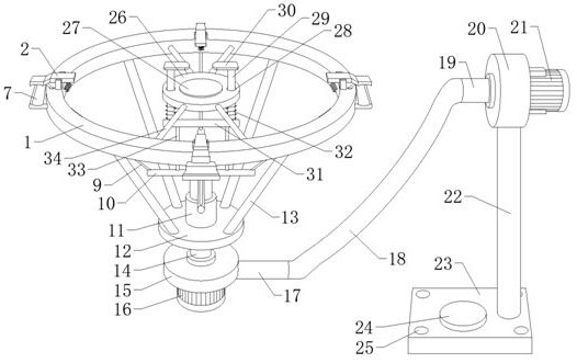
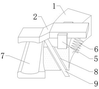
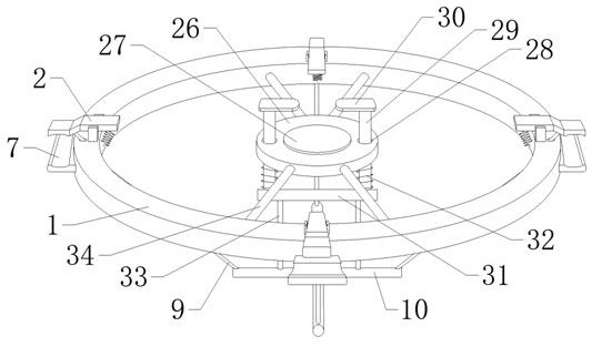
[0027] see Figure 1-6, the present invention provides a new type of processing and positioning turning device for hydraulic fittings, which includes an annular positioning plate 1, the front, rear and left and right sides of the upper surface of the annular positioning plate 1 are provided with clamping plates 2, and the middle part of the clamping plate 2 is provided with The round hole 3 is provided with a support rod 4 inside the round hole 3, and the fron...


PUM


Abstract

The invention discloses a novel machining, positioning and overturning device for hydraulic accessories, and relates to the technical field of accessory machining devices. The novel machining, positioning and overturning device comprises an annular positioning plate, and clamping plates are arranged on the front side, the rear side, the left side and the right side of the upper surface of the annular positioning plate. By arranging the annular positioning plate and arranging clamping plates, round holes, supporting rods, supporting blocks, first springs and clamping seats on the front side, the rear side, the left side and the right side of the annular positioning plate, when an electric push rod retracts, the moving end of the electric push rod can pull four first connecting steel wire ropes to move downwards; the top ends of the four first connecting steel wire ropes pull the opposite ends of the four clamping plates to move downwards, at the moment, the hydraulic accessories placed on the clamping seats can be firmly clamped in the arc-shaped grooves in the clamping plates and the clamping seats, then the clamped and fixed hydraulic accessories can be machined, the multiple hydraulic accessories can be clamped and fixed at a time, clamping and positioning of a large number of hydraulic accessories can be met, and the production efficiency of the hydraulic accessories can be effectively improved.

Description

technical field [0001] The invention relates to a positioning and turning device, in particular to a new processing positioning turning device for hydraulic fittings. Background technique [0002] Hydraulic pressure is a term used in the machinery industry and electromechanical industry. Hydraulic pressure can be used as a power transmission method to become hydraulic transmission. Hydraulic pressure can also be used as a control method, which is called hydraulic control. To transmit power, hydraulic control uses pressure liquid as the control signal transmission mode. The control system composed of hydraulic technology is called hydraulic control system. Hydraulic control usually includes hydraulic open-loop control and hydraulic closed-loop control. Hydraulic closed-loop control is also hydraulic pressure control. Hefu control, which constitutes a hydraulic servo system, usually includes an electro-hydraulic servo system (electro-hydraulic servo system) and a mechanical-hy...

Claims


Application Information

Patent Timeline
Patent Type & Authority Applications(China)
IPC IPC(8): B23Q3/08
CPCB23Q3/082
Inventor 胡鹏胡圣恩陶玉英
Owner 重庆君工装饰工程有限责任公司
Why Eureka
Try Eureka