
Longitudinal rib hollow wall body, hanging nail connecting joint of longitudinal rib hollow wall body and design construction method of longitudinal rib hollow wall body

A technology for connecting nodes and hanging nails, applied in design optimization/simulation, instrumentation, constraint-based CAD, etc., can solve the problems of small prefabricated wall size, low hoisting efficiency, and self-heavy longitudinal rib hollow wall panels, and achieve cost Low, fast installation, reasonable stress effect

Active Publication Date: 2021-10-15
北京市住宅产业化集团股份有限公司
View PDF7 Cites 0 Cited by
  • Summary
  • Abstract
  • Description
  • Claims
  • Application Information

AI Technical Summary

Problems solved by technology

However, this form of longitudinal rib hollow wall panels has a large dead weight, and the size of the prefabricated wall is small. When installing, more longitudinal rib hollow wall panels are required, and the hoisting efficiency is low.

Method used


Image

  • Longitudinal rib hollow wall body, hanging nail connecting joint of longitudinal rib hollow wall body and design construction method of longitudinal rib hollow wall body
  • Longitudinal rib hollow wall body, hanging nail connecting joint of longitudinal rib hollow wall body and design construction method of longitudinal rib hollow wall body
  • Longitudinal rib hollow wall body, hanging nail connecting joint of longitudinal rib hollow wall body and design construction method of longitudinal rib hollow wall body

Examples


Embodiment Construction

[0064] In order to make the technical means, innovative features, goals and effects achieved by the present invention easy to understand, the present invention will be further described below.

[0065] The examples described here are specific specific implementations of the present invention, and are used to illustrate the concept of the present invention. They are all explanatory and exemplary, and should not be construed as limiting the implementation of the present invention and the scope of the present invention. In addition to the embodiments described here, those skilled in the art can also adopt other obvious technical solutions based on the claims of the application and the contents disclosed in the description, and these technical solutions include adopting any obvious changes made to the embodiments described here. Replacement and modified technical solutions.

[0066] In the description of the present invention, it should be noted that the terms "upper", "lower", "i...


PUM


Abstract

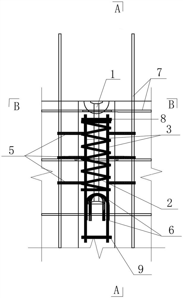
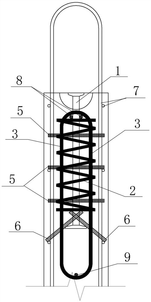
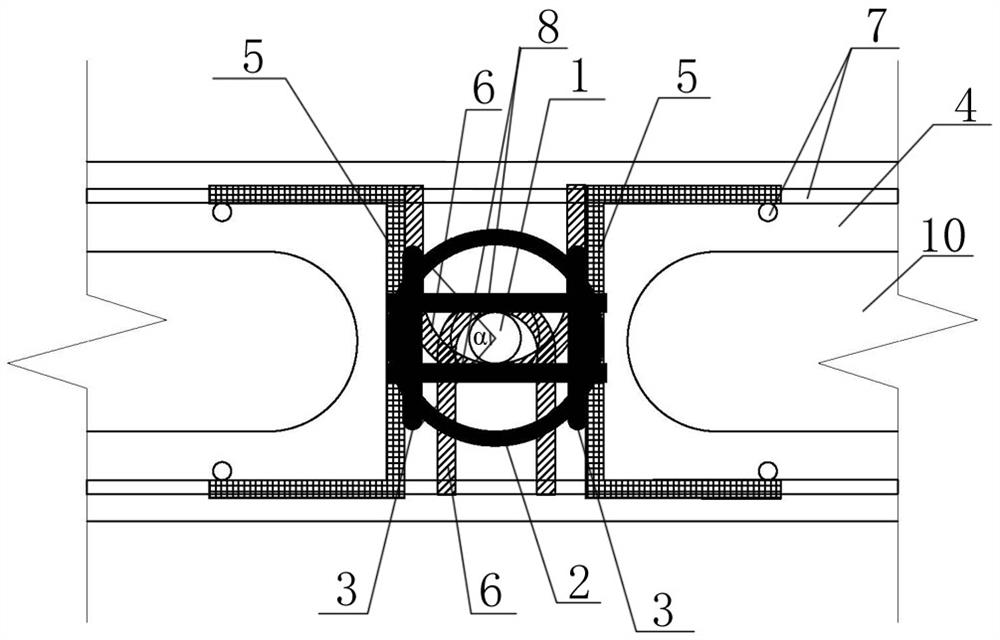
The invention discloses a longitudinal rib hollow wall and a hanging nail connecting joint of the longitudinal rib hollow wall body and a design and construction method of the longitudinal rib hollow wall body, and belongs to the field of building structures. The hanging nail connecting joint comprises hanging nails, constraint stirrups and vertical additional annular steel bars. The hanging nails are vertically arranged in wallboard longitudinal ribs, and the tops of the hanging nails are basically flush with the tops of the wallboard longitudinal ribs. The constraint stirrups are spiral stirrups, and the constraint stirrups are arranged on the upper portion of a prefabricated wallboard around the hanging nails. The number of the vertical additional annular steel bars is two, the vertical additional annular steel bars are symmetrically connected to the outer sides of the constraint stirrups, and the bottoms of the vertical additional annular steel bars are lower than the bottoms of the constraint stirrups. The design method of the hanging nail connecting joint of the longitudinal rib hollow wall is provided for the first time, and a basis is provided for design and production. According to the longitudinal rib hollow wall and the hanging nail connecting joint of the longitudinal rib hollow wall body and the design and construction method of the longitudinal rib hollow wall body, lifting points can be arranged in a longitudinal rib hollow prefabricated wallboard with a through cavity, the dead weight of the longitudinal rib hollow prefabricated wallboard is reduced, the size of the wallboard is reduced, and the installation efficiency is improved. The joint is reasonable in stress, convenient to machine, rapid to install and low in cost.

Description

technical field [0001] The invention belongs to the field of building structures, and in particular relates to a longitudinal rib hollow wall body, a hanging nail connection node and a design and construction method thereof. Background technique [0002] In order to meet the needs of production and construction links such as demoulding, turning, lifting, and installation, longitudinal rib hollow wall panels need to be provided with lifting points. At present, the commonly used hanging points of prefabricated walls mainly include three categories: (1) pre-embedded lifting rings, such as tool rings and steel bar rings; (2) pre-embedded hanging nails; [0003] Commonly used lifting points require a large longitudinal rib area, so the longitudinal rib hollow wall panels are usually set in the form of a small cavity in the upper part and a large cavity in the lower part. However, this form of longitudinal-rib hollow wall panels has a large dead weight, and the size of the prefab...

Claims


Application Information

Patent Timeline
Patent Type & Authority Applications(China)
IPC IPC(8): E04C2/06E04C2/30E04C5/06E04G21/00G06F30/13G06F30/17G06F30/20G06F111/04G06F119/14
CPCE04C2/06E04C2/30E04C5/06E04G21/00G06F30/13G06F30/17G06F30/20G06F2111/04G06F2119/14
Inventor 刘洋杨思忠岑丽丽刘立平袁啸天唐国安王金友王彬彬
Owner 北京市住宅产业化集团股份有限公司
Learn More