
A thermal power plant high-temperature flue gas waste heat recovery device using single-tank molten salt heat exchange

A waste heat recovery device and high-temperature flue gas technology are applied in the direction of indirect heat exchangers, heat exchanger types, and reduction of greenhouse gases. Ease of maintenance, reduce heat loss, and save equipment

Active Publication Date: 2022-03-22
BICHENG SHANGHAI AMPEREX TECH CO LTD
View PDF0 Cites 0 Cited by
  • Summary
  • Abstract
  • Description
  • Claims
  • Application Information

AI Technical Summary

Problems solved by technology

[0003] 1. If the molten salt pump stops, the molten salt heating device will continue to dry and burn out the heating device
[0004] 2. Molten salt contact with air with organic matter will lead to deterioration and smoke
[0005] 3. It is not easy to detect salt leakage in the pipeline of molten salt equipment
[0006] 4. In addition to the above literature records, in actual use, there is also the poor fluidity of the molten salt in the cold molten salt tank, which will lead to difficult retention and solidification problems
[0007] 5. It takes a lot of resources to keep the molten salt tank warm
[0008] 6. After the existing molten salt heat exchange device fails, it is difficult to transfer the molten salt to maintain equipment and other issues

Method used

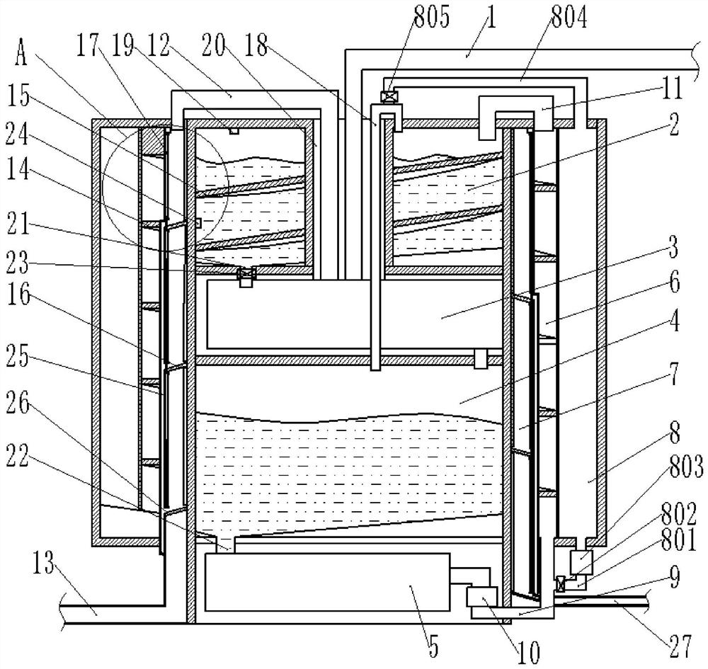
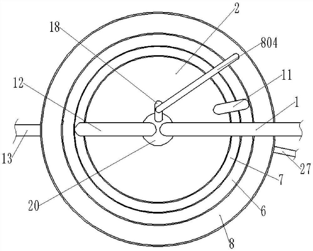
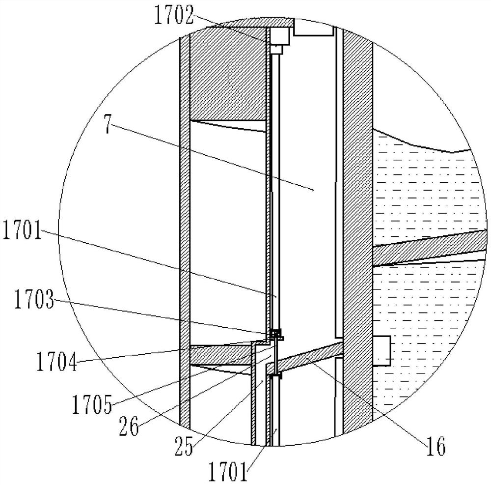

Image

  • A thermal power plant high-temperature flue gas waste heat recovery device using single-tank molten salt heat exchange
  • A thermal power plant high-temperature flue gas waste heat recovery device using single-tank molten salt heat exchange
  • A thermal power plant high-temperature flue gas waste heat recovery device using single-tank molten salt heat exchange

Examples


Embodiment Construction

[0032] In order to make the purpose, technical solutions and advantages of the embodiments of the present invention clearer, the technical solutions in the embodiments of the present invention will be clearly and completely described below in conjunction with the drawings in the embodiments of the present invention. Obviously, the described embodiments It is a part of embodiments of the present invention, but not all embodiments. The components of the embodiments of the invention generally described and illustrated in the figures herein may be arranged and designed in a variety of different configurations.

[0033] The following will be further described in conjunction with specific embodiments. First, the use scene of the present invention will be explained. For the recovery of waste heat from high-temperature flue gas in thermal power plants, thermal power plants work continuously and only shut down during maintenance. Thermal power plants that operate well for half a year or...


PUM


Abstract

The invention provides a thermal power plant high-temperature flue gas waste heat recovery device using a single tank of molten salt heat exchange, belonging to the technical field of molten salt heat exchange, including: hot air inlet pipe, upper cold tank area, molten salt heating area, and lower hot tank zone, hot zone for molten salt, spiral rising cold tank zone, thermal insulation and dust removal zone, and maintenance spare tank zone. On the outer ring of the cylindrical area, the spiral rising cold tank area surrounds the outer ring of the heat preservation and dust removal area. The molten salt flows naturally from the upper cold tank area to the molten salt heating area to avoid the problem of dry burning of the heating device caused by the failure of the molten salt pump. On this basis, this device also solves the problems in the molten salt heat exchange technology, such as the molten salt is in contact with the outside world, the molten salt is easy to leak and difficult to detect, the heat preservation requirement is high, and the molten salt is easy to stay and condense. The entire molten salt heat exchange device has the characteristics of stability and reliability, small heat dissipation, maximum utilization of resources, and convenient maintenance.

Description

technical field [0001] The invention relates to the technical field of molten salt heat exchange, in particular to a thermal power plant high-temperature flue gas waste heat recovery device using a single tank of molten salt for heat exchange. Background technique [0002] Thermal power plants consume 50% of my country's total coal output, and their exhaust heat loss is the largest among all heat losses of power plant boilers, accounting for 80% or more of the total heat loss of boilers. The temperature of the flue gas directly discharged from the furnace is above 400°C. The waste heat recovery of high-temperature flue gas and the reduction of the exhaust gas temperature of the boiler have always been difficult problems in the flue gas treatment technology of thermal power plants. Molten salt heat storage technology is a very promising high-temperature liquid heat transfer and heat storage technology. It has the advantages of good heat transfer performance, low pressure, and...

Claims


Application Information

Patent Timeline
Patent Type & Authority Patents(China)
IPC IPC(8): F28D20/02F23J15/06
CPCF28D20/021F28D20/028F23J15/06Y02E60/14Y02E20/30
Inventor 李亚斌
Owner BICHENG SHANGHAI AMPEREX TECH CO LTD
Learn More