Device and method for detecting sealing performance of transformer expansion tank capsule

A technology of leak detection and transformer oil, which is applied in the direction of fluid tightness test, measuring device, liquid tightness measurement using liquid/vacuum degree, etc. It can solve problems such as inability to maintain pressure for a long time, inaccurate detection, etc. To achieve the effect of convenient air tightness inspection, convenient disassembly and assembly, and strong practicability

Pending Publication Date: 2021-10-15
重庆大唐国际彭水水电开发有限公司
View PDF0 Cites 1 Cited by
  • Summary
  • Abstract
  • Description
  • Claims
  • Application Information

AI Technical Summary

Problems solved by technology

[0005] The air tightness detection of the existing transformer oil pillow capsule mainly depends on the pressure reducing valve of the gas cylinder to judge, and there is a risk that the pressure cannot be maintained for a long time and the detection is inaccurate. Therefore, an air tightness detection device for the transformer oil pillow capsule is urgently needed to solve the problem. above question

Method used


Image

  • Device and method for detecting sealing performance of transformer expansion tank capsule

Examples


Embodiment 1

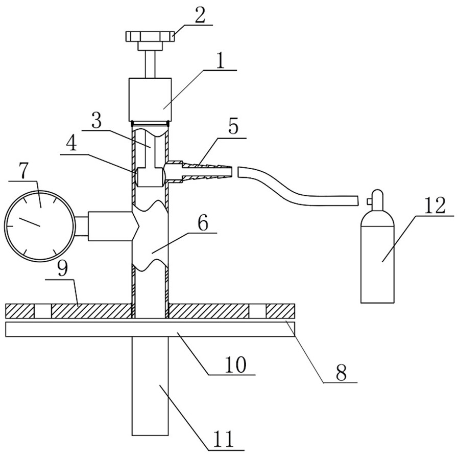
[0032] Such as figure 1 As shown, in this embodiment, a transformer oil conservator capsule leak detection device mainly includes a detection device body 1, a valve 2, a transmission rod 3, a seal 4, an air supply interface 5, an internal pipeline 6, and a pressure gauge 7 Connect the flange 8 with the transformer respirator.

[0033] In this embodiment, the top of the detection device body 1 is provided with a valve 2; the valve 2 is connected to the transmission rod 3; the lower end of the transmission rod 3 is connected to the seal 4; one side of the seal 4 is provided with an air supply interface 5; The middle part of the detection device body 1; the middle part of the detection device body 1 is provided with an internal pipe 6; the side wall of the internal pipe 6 is connected to the pressure gauge 7; the lower end of the detection device body 1 is provided with a transformer respirator connection flange 8.

[0034] In this embodiment, the connecting flange 8 of the pres...

Embodiment 2

[0050] In this embodiment, the top of the detection device body 1 is provided with a valve 2; the valve 2 is connected to the transmission rod 3; the lower end of the transmission rod 3 is connected to the seal 4; one side of the seal 4 is provided with an air supply interface 5; The middle part of the detection device body 1; the middle part of the detection device body 1 is provided with an internal pipe 6; the side wall of the internal pipe 6 is connected to the pressure gauge 7; the lower end of the detection device body 1 is provided with a transformer respirator connection flange 8.

[0051] In this embodiment, the connecting flange 8 of the pressurizer respirator is divided into an upper connecting flange 9 and a lower connecting flange 10 .

[0052] In this embodiment, the upper connecting flange 9 is connected to the lower connecting flange 10 .

[0053] In this embodiment, both the upper connecting flange 9 and the lower connecting flange 10 are connected to the shaf...

Embodiment 3

[0067] In this embodiment, the top of the detection device body 1 is provided with a valve 2; the valve 2 is connected to the transmission rod 3; the lower end of the transmission rod 3 is connected to the seal 4; one side of the seal 4 is provided with an air supply interface 5; The middle part of the detection device body 1; the middle part of the detection device body 1 is provided with an internal pipe 6; the side wall of the internal pipe 6 is connected to the pressure gauge 7; the lower end of the detection device body 1 is provided with a transformer respirator connection flange 8.

[0068] In this embodiment, the connecting flange 8 of the pressurizer respirator is divided into an upper connecting flange 9 and a lower connecting flange 10 .

[0069] In this embodiment, the upper connecting flange 9 and the lower connecting flange 10 are tightly connected.

[0070] In this embodiment, both the upper connecting flange 9 and the lower connecting flange 10 are connected to...


PUM


Abstract

The invention discloses a device and method for detecting the sealing performance of a transformer expansion tank capsule, and the device comprises a detection device body (1), and is characterized in that the top end of the detection device body (1) is provided with a valve (2); the valve (2) is connected with a transmission rod (3); the lower end of the transmission rod (3) is connected with a sealing piece (4); one side of the sealing piece (4) is provided with an air supply interface (5); the air supply interface (5) is arranged in the middle of the detection device body (1); an internal pipeline (6) is arranged in the middle of the detection device body (1); the side wall of the internal pipeline (6) is connected with a pressure gauge (7); and a transformer respirator connecting flange (8) is arranged at the lower end of the detection device body (1). The device has multiple functions, has the functions of inflation, exhaust, pressure maintaining and pressure data reading of the transformer expansion tank capsule, and greatly facilitates the air tightness inspection work of the transformer expansion tank capsule; disassembly and assembly are convenient, detachable parts are connected through threads, and a matched disassembly and assembly tool is arranged.

Description

technical field [0001] The invention relates to the field of oil-immersed transformer capsule detection and maintenance devices, in particular to a transformer oil pillow capsule sealing performance detection device and method. Background technique [0002] Oil conservator is an essential protective device for oil-immersed transformers. At present, capsule-type transformer oil conservators are widely used in power systems. The gas inside the oil conservator capsule communicates with the atmosphere through the moisture absorber, and the bottom surface of the capsule is close to the oil surface in the conservator. There is no air between the capsule and the oil surface. When the oil level changes, the capsule will expand or contract accordingly under the action of oil pressure and atmospheric pressure, and play the role of oil storage and oil replenishment to ensure that the transformer oil chamber is full of oil. , It can also avoid direct contact between the transformer oil ...

Claims


Application Information

Patent Timeline
Patent Type & Authority Applications(China)
IPC IPC(8): G01M3/32
CPCG01M3/3218
Inventor 吕博郭伟王浪
Owner 重庆大唐国际彭水水电开发有限公司
Why Eureka
Try Eureka