Compact power distribution box

A distribution box, compact technology, applied in the direction of substation/power distribution device shell, electrical components, substation/switch layout details, etc., can solve problems such as equipment failure, temperature rise of distribution box, gas accumulation, etc.

Inactive Publication Date: 2021-10-15
黄荣坤
View PDF0 Cites 0 Cited by
  • Summary
  • Abstract
  • Description
  • Claims
  • Application Information

AI Technical Summary

Problems solved by technology

[0003] Aiming at the deficiencies in the prior art, the object of the present invention is to provide a compact distribution box. When using the distribution box in hot summer, the electrical components in the distribution box generate heat, and the heat rises in the form of hot air, which is easy to It causes the gas to accumulate between the cover plate and the baffle plate, so that it cannot be removed in time, so that the temperature in the distribution box rises accordingly, resulting in the problem that the equipment cannot operate normally

Method used


Image

  • Compact power distribution box
  • Compact power distribution box
  • Compact power distribution box

Examples


Embodiment 1

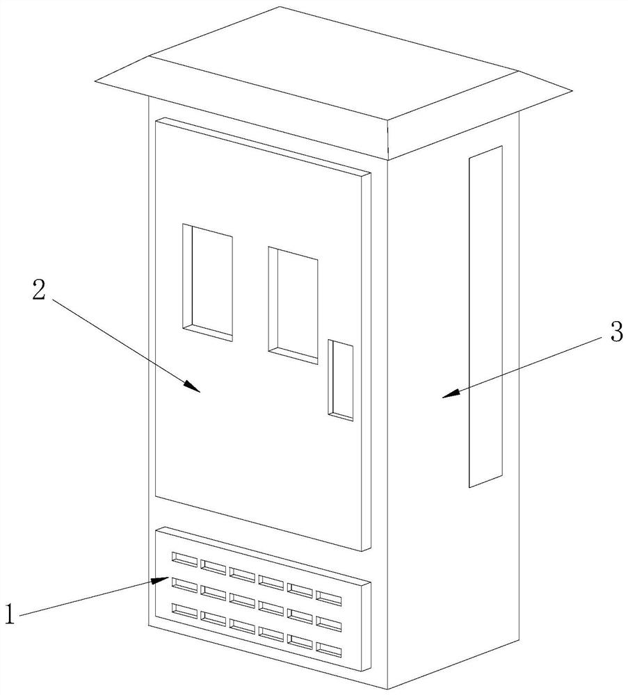
[0028] as attached figure 1 to attach Figure 7 Shown:

[0029] The present invention provides a compact distribution box, the structure of which includes: an exhaust plate 1, a door leaf 2, and a box body 3, the rear end of the exhaust plate 1 is embedded in the inner side of the box body 1, and the door leaf 2 is hinged Installed in the front of the box body 3.

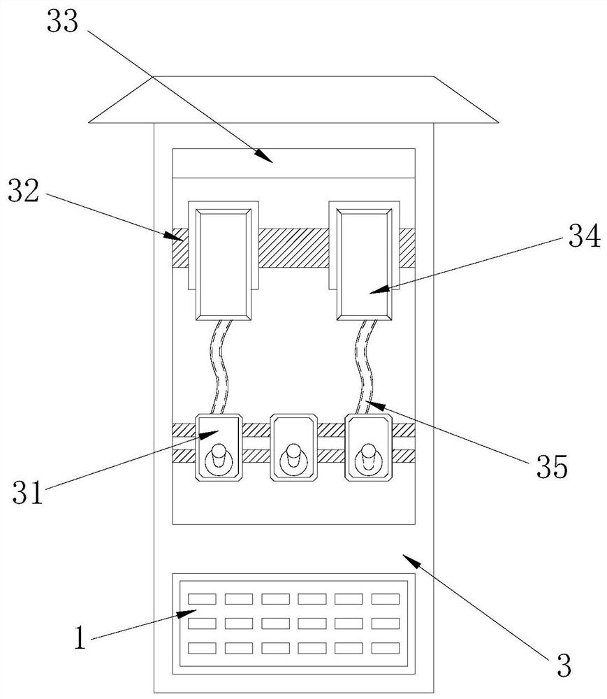
[0030] Wherein, the box body 3 includes a protective element 31, a mounting plate 32, a telescopic device 33, a display 34, and a connecting wire 35. The rear end surface of the protective element 31 is bolted to the front end surface of the mounting plate 32, and the mounting plate 32 and the box body 3 are integrated structures, the lower end of the telescopic device 33 is embedded in the inner side of the box body 3, the display 34 is detachably installed in front of the mounting plate 32, and the front surface of the display 34 is embedded with the door leaf 2 The connecting wire 35 is installed between the ...

Embodiment 2

[0039] as attached Figure 7 As shown: the moving mechanism 223 includes a flexible plate a1, a buffer mechanism a2, a support rod a3, a connecting rod a4, an exhaust port a5, and a U-shaped groove a6. The flexible plate a1 is embedded in the inner side of the U-shaped groove a6, and The upper end surface of the flexible plate a1 is fixedly connected to the lower end surface of the connecting rod a4, the lower end surface of the buffer mechanism a2 is embedded and connected to the upper end surface of the connecting rod a4, and the support rod a3 is installed on both sides of the connecting rod a4 , the exhaust hole a5 is installed between the U-shaped grooves a6, the flexible plate a1 is made of spring steel, and the flexible plate a1 has elastic properties, so after the connecting rod a4 moves, it can pass through the elastic properties of the flexible plate a1 Drive the connecting rod a4 back to its original state.

[0040] as attached Figure 8 to attach Figure 9 Shown...


PUM


Abstract

The invention provides a compact power distribution box which structurally comprises an exhaust plate, a door leaf and a box body. The rear end of the exhaust plate is embedded into the inner side of the box body, and the door leaf is installed in front of the box body through a hinge. In the running process of the compact power distribution box, heat in the box body rises towards the direction of a cover plate in the form of hot air, so that the hot air can be utilized to push a moving plate to move upwards, a button can extrude a switch, and the switch controls the starting of a driving shaft so as to dissipate the heat of the rising hot air; meanwhile, air is utilized to impact a buffer mechanism through an exhaust port, an opening of a moving mechanism is opened, and the air enters the inner side of the cover plate; the cover plate is trapezoidal, and the exhaust hole is formed in the lower end of the cover plate, so that the box body can be waterproof through the cover plate, the hot air in the box body can be exhausted through the exhaust hole, and the phenomenon that the temperature of the box body rises due to the fact that the hot air is gathered between the cover plate and a baffle and cannot be exhausted in time, is avoided.

Description

technical field [0001] The invention relates to the technical field of power distribution and utilization, in particular to a compact power distribution box. Background technique [0002] As we all know, the distribution box is assembled in a closed metal cabinet through switchgear, protective appliances and other components to form a distribution box. The distribution box is small in size and stable and reliable in operation. In the working state, a prompt signal will be generated, so the application of the distribution box is relatively common, but the compact distribution box in the prior art, because the distribution box is compact, the heat dissipation channel is relatively narrow, so that the exhaust capacity Limited, when the distribution box is used in hot summer, the electrical components in the distribution box will generate heat, and the heat will rise in the form of hot air, which will easily cause the gas to accumulate between the cover and the baffle, so that i...

Claims


Application Information

Patent Timeline
Patent Type & Authority Applications(China)
IPC IPC(8): H02B1/46H02B1/56H02B1/28
CPCH02B1/46H02B1/565H02B1/28
Inventor 黄荣坤
Owner 黄荣坤
Why Eureka
Try Eureka