
Main shaft tool loosening force unloading mechanism based on floating oil cylinder

A technology of loosening the knife and oil cylinder, applied in the field of machine tools, can solve the problems of reducing bearing life, stress can not be eliminated immediately, bearing load increase, etc., to achieve the effect of ensuring support accuracy, reducing stress load and strain

Pending Publication Date: 2021-10-19
通用技术齐齐哈尔二机床有限责任公司
View PDF0 Cites 0 Cited by
  • Summary
  • Abstract
  • Description
  • Claims
  • Application Information

AI Technical Summary

Problems solved by technology

When the spindle is loosened, the spindle bearing has to bear an axial load of up to 50-60kN, which will cause 0.3-0.5mm (actual test value) stress deformation between the bearing ball and the raceway. When the tool is released, although the bearing It is no longer subject to the tool release force, but the stress generated by the tool release force on the spindle bearing cannot be eliminated immediately. Therefore, when the tool release is completed and the spindle rotates, an additional internal stress relative to more than 60% of the tool release force will be added. According to the bearing The life calculation formula, the bearing load increases, will greatly reduce the bearing life
At the same time, since the strain of the balls and the raceway of the spindle bearing cannot be eliminated immediately, the position of the spindle in the axial direction also changes greatly during processing, which seriously affects the machining accuracy of the spindle.

Method used


Image

  • Main shaft tool loosening force unloading mechanism based on floating oil cylinder
  • Main shaft tool loosening force unloading mechanism based on floating oil cylinder

Examples


Embodiment Construction

[0013] The present invention will be further described below in conjunction with accompanying drawing:

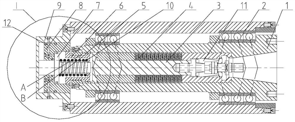
[0014] Depend on figure 1 As shown, a main shaft loosening force unloading mechanism based on a floating oil cylinder includes a main shaft 1 and a reset sleeve 9. The outside of the main shaft 1 is supported on the main shaft support through the main shaft bearing 2. Clamping jaws 11 are connected to the knife bar 3, and disc spring group 4 is arranged on the outside of the knife bar 3, and the two ends of the disc spring group 4 are provided with bushings, wherein the end of the bushing on the left side rests on the step at the end of the knife bar 3 On the right, the end of the sleeve on the right is on the step of the main shaft 1. The end of the main shaft 1 is connected with a first unloading sleeve 5 by screws.

[0015] The reset sleeve 9 is fixed on the end of the main shaft support, and the inside of the reset sleeve 9 is provided with a knife loosening oil cylin...


PUM


Abstract

The invention relates to a main shaft tool loosening force unloading mechanism based on a floating oil cylinder. The main shaft tool loosening force unloading mechanism mainly solves the problem that the thrust generated in the existing main shaft tool loosening process can shorten the service life of a bearing and affect the machining precision of a main shaft. The main shaft tool loosening force unloading mechanism is characterized in that a disc spring set (4) is arranged outside a tool pull rod (3), and the end of a main shaft (1) is connected with a first unloading sleeve (5); and a tool loosening oil cylinder (8) is arranged inside a reset sleeve (9), a tool loosening piston (7) is arranged inside the tool loosening oil cylinder (8), the interior of the right end of the tool loosening oil cylinder (8) is connected with a second unloading sleeve (6), and the second unloading sleeve (6) is matched with the first unloading sleeve (5) through a step. According to the main shaft tool loosening force unloading mechanism, the tool loosening thrust generated by the oil cylinder is converted into the internal force of the main shaft through the floating oil cylinder, the main shaft bearing does not bear the external force of main shaft tool loosening any more, the machining precision of the main shaft is improved, and the service life of the bearing is prolonged.

Description

technical field [0001] The invention relates to the field of machine tools, in particular to a spindle tool release force unloading mechanism based on a floating oil cylinder. Background technique [0002] For high-speed, high-precision CNC machine tools and milling heads, the accuracy and stability of the spindle are the key. When the spindle is released, the spindle bearing can withstand an axial release force of up to 50-60kN. According to the formula L h =10 6 / 60n(C / P) 3 , where L h -Bearing life (h); n-bearing rotating speed (rpm); C-bearing basic dynamic load rating (N); P-bearing load (N). When the spindle is loosened, the spindle bearing has to bear an axial load of up to 50-60kN, which will cause 0.3-0.5mm (actual test value) stress deformation between the bearing ball and the raceway. When the tool is released, although the bearing It is no longer subject to the tool release force, but the stress generated by the tool release force on the spindle bearing cann...

Claims


Application Information

Patent Timeline
Patent Type & Authority Applications(China)
IPC IPC(8): B23Q3/157
CPCB23Q3/157
Inventor 王海军王莘澳郭生崔成
Owner 通用技术齐齐哈尔二机床有限责任公司
Learn More