A commutator hook chamfering device

A technology of a chamfering device and a commutator, which is applied in the field of commutators, can solve the problems affecting the chamfering of the hook of the commutator and the absence of the hook of the commutator, and achieve the effects of improving the chamfering efficiency and reducing the positioning error.

Active Publication Date: 2022-05-17
浙江利丰电器有限公司
View PDF8 Cites 0 Cited by
  • Summary
  • Abstract
  • Description
  • Claims
  • Application Information

AI Technical Summary

Problems solved by technology

[0007] In view of the above-mentioned shortcomings existing in the prior art, the present invention provides a commutator hook chamfering device, which can effectively solve certain errors that are prone to occur in the prior art, so that the follow-up commutator hook is not squeezed with the arc. Correspondence of the groove, which in turn affects the problem of chamfering the hook of the commutator

Method used


Image

  • A commutator hook chamfering device
  • A commutator hook chamfering device
  • A commutator hook chamfering device

Examples


Embodiment

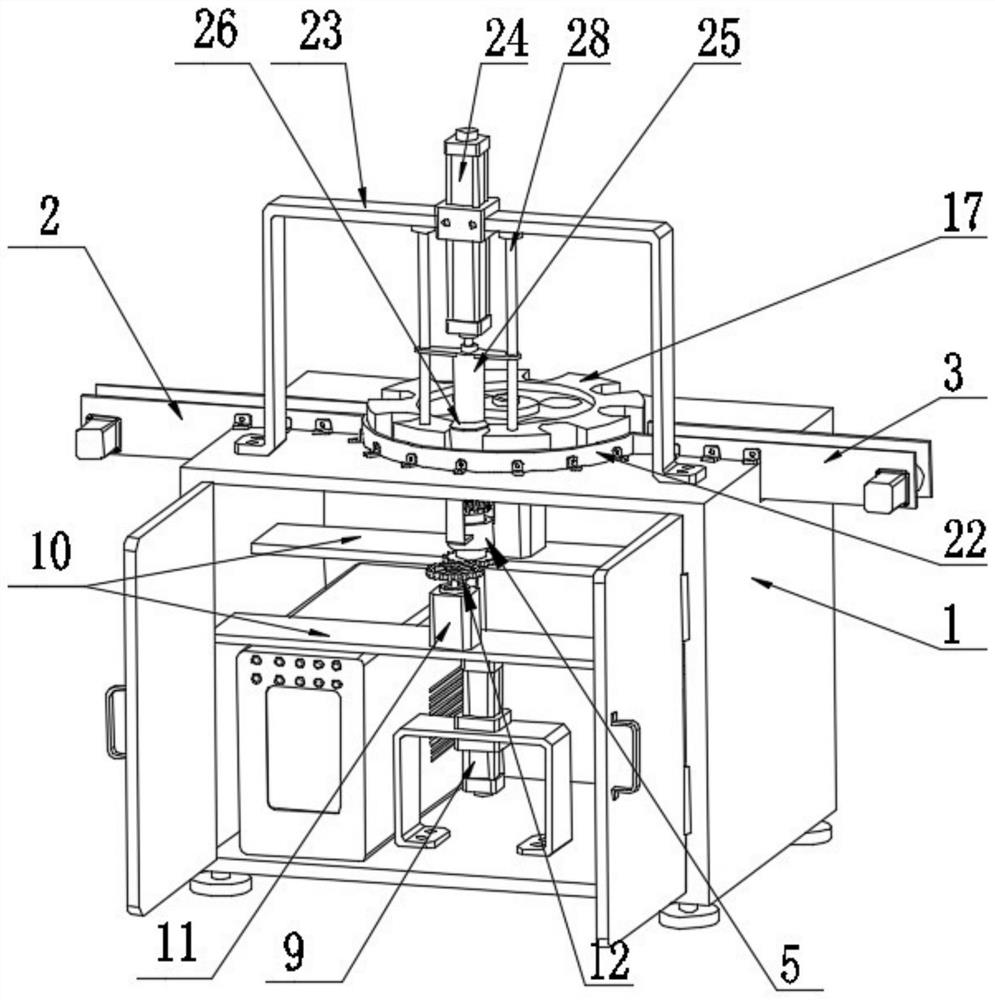
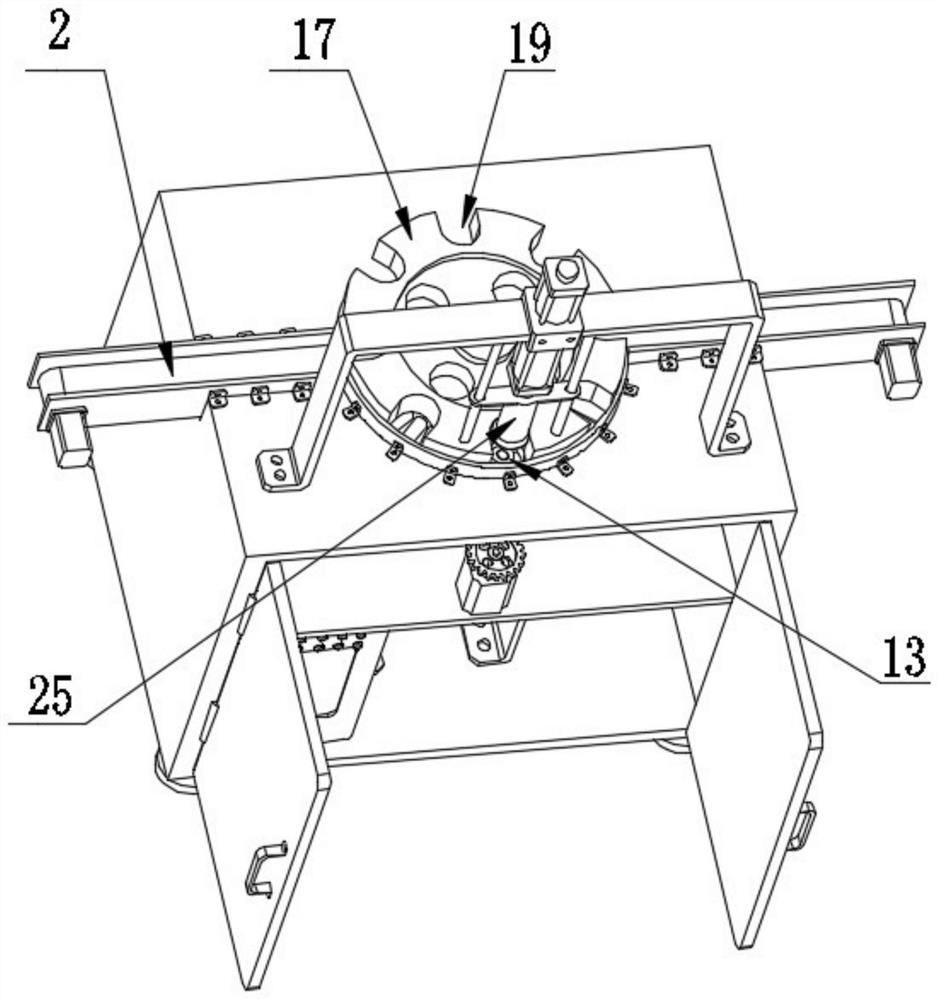
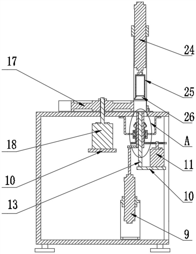
[0036] A commutator hook chamfering device of this embodiment, refer to Figure 1-9: Including the machine body 1, the left and right parts of the body 1 are respectively provided with a feeding conveyor belt 2 and an unloading conveyor belt 3; There is a chamfering hole 4 on the top of the body, a chamfering mechanism is provided on the front side of the top of the body 1, and a positioning mechanism is arranged in the front of the body 1. The positioning mechanism includes two sets of front and rear symmetrical brackets fixed in the upper layer of the front of the body 1 and aligned with the chamfering. The swivel 5 coaxial with the angular hole 4, the rotating drum 6 connected in the rotating ring 5, the frustum part 7 arranged on the top of the rotating drum 6 and communicating with the rotating drum 6, and the outer wall of the circumference of the bottom of the rotating drum 6 The transmission gear 8, the lifting cylinder 9 fixed in the lower layer of the front part of t...


PUM


Abstract

The invention relates to the technical field of commutators, in particular to a chamfering device for hooks of a commutator, which includes a machine body. The left and right parts of the machine body are respectively provided with a feeding conveyor belt and an unloading conveyor belt. There is a transfer mechanism between the material conveyor belts, a chamfering hole is provided at the front of the top side of the machine body, a chamfering mechanism is provided at the front side of the top of the machine body, and a positioning mechanism is arranged in the front part of the machine body; the invention rotates the drum at a slow speed, The commutator and the frustum of the cone are relatively rotated, so that the hook of the commutator is effectively snapped into the hook groove of the frustum of the cone, that is, the matching between the hook of the commutator and the hook groove of the frustum of the cone is effectively ensured, and the positioning error, thereby effectively reducing the impact on the chamfering of the commutator hook; at the same time, through the sequential cooperation of the feeding conveyor belt, transfer mechanism, chamfering mechanism, positioning mechanism and unloading conveyor belt, the continuous and automatic adjustment of the commutator hook is realized. Chamfering, improve chamfering efficiency.

Description

technical field [0001] The invention relates to the field of commutators, in particular to a chamfering device for a hook portion of a commutator. Background technique [0002] After the commutator is pressed together with the commutator copper sheet and bakelite powder, the top of the commutator copper sheet is milled to narrow it to form the commutator hook, and then the commutator hook is bent in the next bending process Finally, the welding wire hook of the commutator is formed. Due to machining, sharp corners are inevitably formed at the corners where the outer surface of the hook portion of the commutator meets the left and right sides, and this will obviously affect the subsequent use of the commutator, so the above-mentioned corners need to be chamfered. The currently used methods include polishing with a buffing wheel, rolling with a rolling wheel, and filing with a file, but each hook needs to be chamfered separately, resulting in low processing efficiency. [00...

Claims


Application Information

Patent Timeline
Patent Type & Authority Patents(China)
IPC IPC(8): B26D7/00B26D7/06B26D7/32H01R43/06
CPCB26D7/00B26D7/0625B26D7/32H01R43/06
Inventor 张余明
Owner 浙江利丰电器有限公司
Why Eureka
Try Eureka