Warp knitting machine needle piece

A technology of warp knitting machines and needles, which is applied in the field of warp knitting, and can solve problems such as increased wear, reduced economic benefits of enterprises, and increased force on needles, and achieves high machine speed, improved production efficiency, and stable knitting process Effect

Active Publication Date: 2021-10-19
广州市赛德精工科技有限公司
View PDF8 Cites 0 Cited by
  • Summary
  • Abstract
  • Description
  • Claims
  • Application Information

AI Technical Summary

Problems solved by technology

Nowadays, the operating speed of high-speed warp knitting machines can reach more than 4400r / min. With the continuous improvement of the operating speed of high-speed warp knitting machines, and at the same time, the wear and tear on the needle parts of the new environmentally friendly yarns that appear now has increased, resulting in needles designed according to traditional methods. The parts cannot adapt to the latest raw materials and high-speed operating conditions, the service life is greatly reduced, and the economic benefits of the enterprise are significantly reduced
The statistics and analysis of the wear of the needle parts show that the wear of the needle parts mainly occurs in the needle back and the needle groove. Because there are stress mutation points on the contour lines of the needle back and the needle groove and the resistance in the loop forming process is large, the yarn is in the process of stripping and looping. The movement process of unwinding produces a large friction force on the back of the needle and the needle groove, so that the force on the needle at these two positions increases sharply during the coil change process, and the wear is intensified

Method used


Image

  • Warp knitting machine needle piece
  • Warp knitting machine needle piece
  • Warp knitting machine needle piece

Examples


Embodiment Construction

[0034] The present invention will be further described below in conjunction with the accompanying drawings of the description.

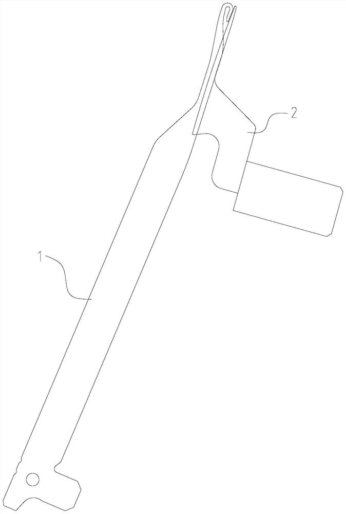
[0035] Such as figure 1 As shown, a warp knitting machine needle includes a grooved needle 1 and a needle core 2 matched therewith. The grooved needle 1 cooperates with the needle core 2 to realize knitting. The present invention is described for the slotted needle 1 whose model is 4341, and other types of slotted needles are also applicable to the inventive design method.

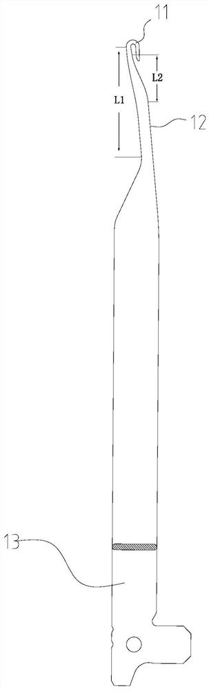
[0036] Such as figure 2 As shown, the slotted needle 1 includes a needle hook 11 , a needle bar 12 and a stitch 13 . The present invention optimizes the needle back contour area L1 and the needle groove contour area L2 of the groove needle, the needle back contour curve of the groove needle is composed of more than one function curve, and the needle groove contour curve of the groove needle is composed of more than one function curve , that is, to optimize the contour line fo...


PUM


Abstract

The invention discloses a warp knitting machine needle piece. A motion abrasion area contour curve of the needle piece is composed of more than one function curve. According to the principle, through research and analysis, a function curve is used for optimizing a motion abrasion area contour curve of the needle piece, the acceleration change of a coil in the knocking-over process can be optimized, the positive pressure of yarn acting on the needle piece is reduced, and the effects of reducing abrasion of the needle piece and prolonging the service life of the needle piece are achieved.

Description

technical field [0001] The invention relates to the field of warp knitting, in particular to needles for warp knitting machines. Background technique [0002] The traditional warp knitting machine needle design method is to connect the functional parts of the needle through standard geometric figures such as arcs and straight lines, that is, the outer contour of the needle is formed by connecting straight lines and arcs. The traditional design method of needle parts is mainly aimed at the operation speed of the warp knitting machine at 3000 rpm or below. With the increase of the operation speed of the warp knitting machine, higher design requirements are put forward for the needle parts. Nowadays, the operating speed of high-speed warp knitting machines can reach more than 4400r / min. With the continuous improvement of the operating speed of high-speed warp knitting machines, and at the same time, the wear and tear on the needle parts of the new environmentally friendly yarns...

Claims


Application Information

Patent Timeline
Patent Type & Authority Applications(China)
IPC IPC(8): D04B35/02
CPCD04B35/02
Inventor 陈弘
Owner 广州市赛德精工科技有限公司
Why Eureka
Try Eureka