Waterway sliding switching device and water outlet device
A switching device and waterway technology, which is applied in the field of kitchen and bathroom, can solve the problems of laborious switching, large operating force, etc., and achieve the effect of stable and reliable switching, small switching force, and reasonable waterway layout
- Summary
- Abstract
- Description
- Claims
- Application Information
AI Technical Summary
Problems solved by technology
Method used
Image
Examples
Embodiment 1
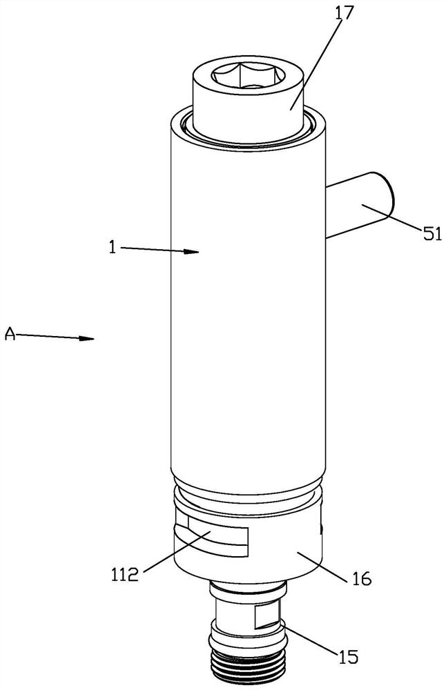
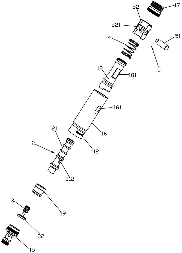
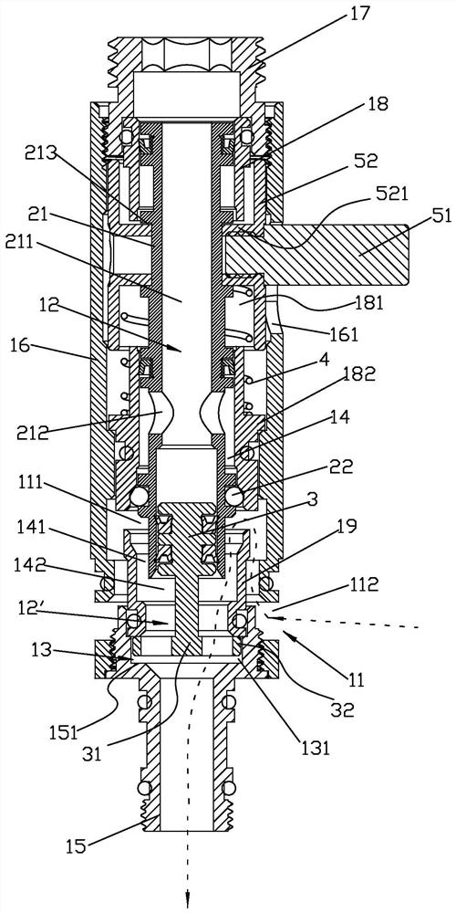
[0054] Please check Figure 1 to Figure 4 , the dotted line with arrows in the figure indicates the direction of water flow. The waterway sliding switching device A includes a valve body part 1 , a sliding part 2 , a force receiving part 3 , a reset elastic body 4 and an operating part 5 . The valve body part 1 is provided with a water inlet 11 and two water diversions 12, 12', and the sliding part 2 can be slidably connected in the valve body part 1 to switch the two water diversions 12, 12' through the sliding to connect to the water inlet 11; The stressed part 3 is arranged in the valve body part 1, it isolates the two divided waterways 12 and cooperates with the two divided waterways 12, 12', so that the water flow in the two divided waterways 12, 12' can act on the stressed part 3 to make it Under the force of water, the sliding part 2 and the force-bearing part 3 can slide relative to each other, and the valve body part 1 is provided with a limit mechanism 13 that limit...
Embodiment 2
[0063] Please check Figure 8 to Figure 11 , the dotted line with arrows in the figure indicates the direction of water flow. It differs from Embodiment 1 in that: the valve body part 1 of the waterway sliding switching device A' includes a second housing 16' and a shaft sleeve 18 sealed and fixed in the second housing 16', the second housing The lower part of 16' is sealed and fixedly connected to the upper part of the shaft sleeve 18, the shaft sleeve 18 cooperates with the second housing 16' and is provided with the above-mentioned installation cavity 14. The second joint 17 is fixed in the second housing 16' and the second joint is connected to the second housing, and the second housing 16' is provided with a second step 162 facing the second joint; The end face is spaced from the second step of the second housing, and the space cooperates to form a limiting groove. The first water distribution channel 12 has an inner part 211 located in the sliding sleeve 21 and the wat...
PUM
 Abstract
Description
Claims
Application Information
 - R&D
- Intellectual Property
- Life Sciences
- Materials
- Tech Scout
- Unparalleled Data Quality
- Higher Quality Content
- 60% Fewer Hallucinations
Browse by: Latest US Patents, China's latest patents, Technical Efficacy Thesaurus, Application Domain, Technology Topic, Popular Technical Reports.
© 2025 PatSnap. All rights reserved.Legal|Privacy policy|Modern Slavery Act Transparency Statement|Sitemap|About US| Contact US: help@patsnap.com


