
Closed cooling tower

A closed cooling tower, water cooling box technology, applied in water shower coolers, direct contact heat exchangers, heat exchange equipment, etc. question

Inactive Publication Date: 2021-10-19
甘肃三元乳业有限公司
View PDF5 Cites 0 Cited by
  • Summary
  • Abstract
  • Description
  • Claims
  • Application Information

AI Technical Summary

Problems solved by technology

[0004] The purpose of the present invention is to: when the above-mentioned existing closed cooling tower is in use, it is necessary to use a spray pump to spray water to the coil pipe through the nozzle. The water will wash down the scale on the coil, and then enter the spray pump, which will easily cause the blockage of the spray pump, thus affecting the cooling of the coil. In addition, the fans of the existing closed cooling tower are usually arranged at the top of the cooling tower. When the cooling tower is working, part of the water will evaporate from the fan outlet, which will affect the heat exchange effect, and a large amount of debris will enter the tower body from the fan outlet, adhere to the heat exchanger or be submerged in the water collection tank, which will affect the heat exchange effect. The problem of certain influence, the present invention provides a kind of closed cooling tower

Method used


Image

  • Closed cooling tower

Examples


Embodiment 1

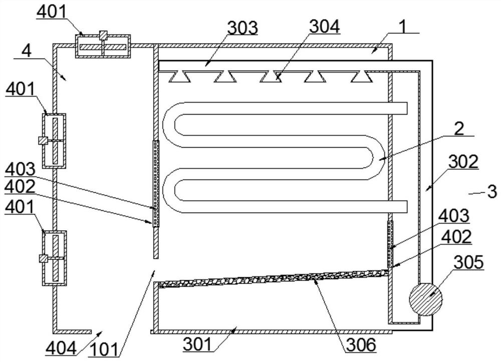
[0020] The structure of this embodiment, such as figure 1 As shown, a closed cooling tower includes a water-cooled box 1, a coil pipe 2 fixed in the middle of the water-cooled box 1, and a water spray device 3. A water tank 301 , a filter plate 306 is fixed between the water collecting tank 301 and the water cooling box 1 , and an air cooling box 4 independent from the water cooling box 1 is fixed on the left outer wall of the water cooling box 1 .

[0021] When the water washes down the scale on the coil 2, the water enters the water collecting tank 301, and the scale is intercepted by the filter plate, preventing the scale from entering the water collecting tank 301 and then entering the spray pump, causing the spray pump to be blocked; independent of the water cooling box 1 The fixed air-cooled box 4 prevents water from evaporating directly from the fan 401 port, which affects the heat exchange effect, and also prevents sundries from directly entering the water-cooled box 1...

Embodiment 2

[0023] In this embodiment, on the basis of Embodiment 1, further, the water spraying device 3 further includes a water delivery pipe 302 that is connected and fixed at one end to the water collection tank 301 and bent vertically upwards, and the other end of the water delivery pipe 302 is connected and fixed There is a water spray pipe 303 extending horizontally into the water cooling tank 1 and located on the upper side of the coil pipe 2. The bottom wall of the water spray pipe 303 is connected and fixed with 2 to 8 nozzles 304, and the bottom end of the water delivery pipe 302 is connected and fixed. There is a water spray pump 305, and the water spray pump 305 pumps the water in the water collection tank 301 into the water delivery pipe 302 and the water spray pipe 303, and then sprays it on the coil pipe 2 through the nozzle 304 to cool down, and the sprayed water falls into the water collection tank 301 Recycling within, saving resources.

Embodiment 3

[0025] In this embodiment, on the basis of Embodiment 1, further, the filter plate 306 is a slope-shaped structure inclined toward the left wall of the water-cooled box 1, and the wall of the water-cooled box 1 where the low end of the filter plate 306 is connected is opened. The first miscellaneous discharge port 101 , the first miscellaneous discharge port 101 communicates with the air-cooled box 4 , after the scale falls on the filter plate 306 , it slides down through the slope and is discharged from the first miscellaneous discharge port 101 .


PUM


Abstract

The invention discloses a closed cooling tower. The closed cooling tower comprises a water cooling tank, a coil pipe fixed in the middle of the water cooling tank and a water spraying device, wherein the water spraying device comprises a header tank fixed to the lower side of the bottom wall of the water cooling tank in a communicated mode, a filter plate is fixed between the header tank and the water cooling tank, and an air cooling tank independently separated from the water cooling tank is fixed to the outer wall of the left side of the water cooling tank. When water flushes off scale on the coil pipe, the water enters the header tank, the scale is intercepted by the filter plate, and the situation that the scale enters the header tank and then enters a spraying pump, and consequently the spraying pump is blocked is avoided; and the air cooling tank is independently fixed to the water cooling tank, so that water is prevented from being directly evaporated from a fan opening to influence the heat exchange effect, and impurities are also prevented from directly entering the water cooling tank from the fan opening to influence the heat exchange effect to a certain extent.

Description

technical field [0001] The invention relates to the field of production cooling devices, in particular to a closed cooling tower. Background technique [0002] As a cooling device, cooling towers are currently widely used in various equipment, such as electric furnace induction heating equipment, central air conditioning, hydraulic systems, air compressors, injection molding machines, boilers, etc. Most of them are combined with air cooling and water cooling, and the cooling water is sprayed through the nozzle. On the copper tube cooler, the cooling water exchanges heat with the cooling liquid in the copper tube cooler, the temperature of the cooling water rises, and the temperature of the cooling liquid in the copper tube cooler decreases, so as to achieve the purpose of cooling. [0003] At present, when the existing closed cooling tower is in use, it is necessary to use a spray pump to spray water on the coil through the nozzle. The scale is washed down and then enters t...

Claims


Application Information

Patent Timeline
Patent Type & Authority Applications(China)
IPC IPC(8): F28C1/14F28F19/01F28F25/04F28F25/10
CPCF28C1/14F28F19/01F28F25/04F28F25/10F28C2001/145
Inventor 李俊
Owner 甘肃三元乳业有限公司
Learn More