
Display panel, manufacturing method thereof, and display device

A technology for display panels and display parts, applied to static indicators, instruments, nonlinear optics, etc., can solve problems such as short-circuit burns, and achieve the effect of reducing alignment accuracy

Active Publication Date: 2022-01-25
HKC CORP LTD
View PDF0 Cites 0 Cited by
  • Summary
  • Abstract
  • Description
  • Claims
  • Application Information

AI Technical Summary

Problems solved by technology

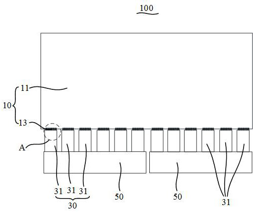
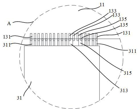
[0003] The main purpose of this application is to provide a display panel, which aims to solve the problem of short-circuit burns after the two high-voltage electrodes are biased when the display panel is subjected to false voltage

Method used


Image

  • Display panel, manufacturing method thereof, and display device
  • Display panel, manufacturing method thereof, and display device
  • Display panel, manufacturing method thereof, and display device

Examples


Embodiment Construction

[0034] The following will clearly and completely describe the technical solutions in the embodiments of the present application with reference to the accompanying drawings in the embodiments of the present application. Obviously, the described embodiments are only part of the embodiments of the present application, not all of them. Based on the embodiments in this application, all other embodiments obtained by persons of ordinary skill in the art without creative efforts fall within the protection scope of this application.

[0035] It should be noted that all directional indications (such as up, down, left, right, front, back...) in the embodiments of the present application are only used to explain the relationship between the components in a certain posture (as shown in the figure). Relative positional relationship, movement conditions, etc., if the specific posture changes, the directional indication will also change accordingly.

[0036] In this application, unless otherw...


PUM

PropertyMeasurementUnit
widthaaaaaaaaaa

Abstract

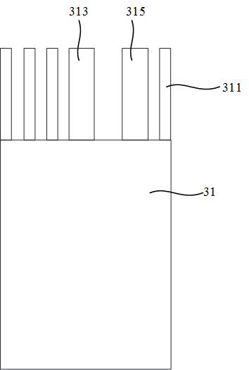
The present application discloses a display panel, a manufacturing method thereof, and a display device. The display panel includes an array substrate and a driver. The array substrate includes a display part and a binding part. The binding part includes a plurality of binding electrodes arranged at intervals. The component includes a driving part, the driving part is provided with a plurality of driving electrodes arranged at intervals, and the plurality of binding electrodes include a first high-voltage electrode group and a second high-voltage electrode group adjacently arranged, and the first high-voltage electrode group includes at least Two first high-voltage electrodes, the second high-voltage electrode group includes at least two second high-voltage electrodes spaced apart, one of the two adjacent driving electrodes is crimped and fixed with the corresponding at least two first high-voltage electrodes, and the other It is crimped and fixed to at least two corresponding second high-voltage electrodes, and the distance between the two driving electrodes is greater than the distance between the first high-voltage electrode group and the second high-voltage electrode group. The display panel of the technical solution of the present application can improve the problem of short-circuit burn caused by voltage bias.

Description

technical field [0001] The present application relates to the field of display technology, in particular to a display panel, a manufacturing method thereof, and a display device. Background technique [0002] With the development of display technology, in order to improve the visual experience, the borders of display products on the market are becoming narrower and narrower, which reduces the bonding area (Bonding) of the array substrate in the display panel. However, the number of signal electrodes (Pin) for electrical connection set in the bonding area is relatively large, and the distance between the two signal electrodes is small, which is used to electrically connect the bonding area and the chip-on-chip of the external main board. There are also many signal electrodes, which correspond to the signal electrodes in the binding area one by one. Before the chip-on-chip film is connected to the array substrate in the production process, the quality test of the chip-on-chip...

Claims


Application Information

Patent Timeline
Patent Type & Authority Patents(China)
IPC IPC(8): G02F1/133G02F1/1343
CPCG02F1/13306G02F1/134309
Inventor 项振杨琳莉李荣荣
Owner HKC CORP LTD
Learn More