Eureka AIR delivers breakthrough ideas for toughest innovation challenges, trusted by R&D personnel around the world.

Ship cabin rain falling type air supply and return system and ship

A wind system and cabin technology, which is applied to the rain-drop air supply and return system of the ship cabin and the ship field, which can solve the problem of high noise at the air outlet of the air distributor, the inability to achieve privacy in the living environment, and the poor ventilation grille, etc. problems, to achieve the effect of uniform air flow, simple installation and layout, and improved comfort and experience

Pending Publication Date: 2021-10-22
中船邮轮科技发展有限公司
View PDF5 Cites 0 Cited by
  • Summary
  • Abstract
  • Description
  • Claims
  • Application Information

AI Technical Summary

Problems solved by technology

[0003] As far as the existing cabin air supply path is concerned, the general ship is to install the air distributor on the ceiling and supply air through the outlet of the air distributor; as far as the existing cabin return air path is concerned, it is generally through the cabin door However, as customers (ship owners, especially mid-to-high-end passenger ships) and passengers continue to increase their living environment requirements, this approach is becoming more and more unsatisfactory
Although this method is simple, its disadvantages are: 1. The air outlets are concentrated, the air is not uniform, the temperature difference inside the room is large in a short period of time, and the comfort is poor; 2. The air distributor protrudes from the ceiling, which reduces the net height and reduces Unsightly; 3. The noise at the air outlet of the air distributor is relatively loud; 4. The ventilation grille is set on the door of the cabin, and the appearance is not beautiful; 5. Since the ventilation grid on the cabin door cannot be well The environment cannot achieve high privacy

Method used

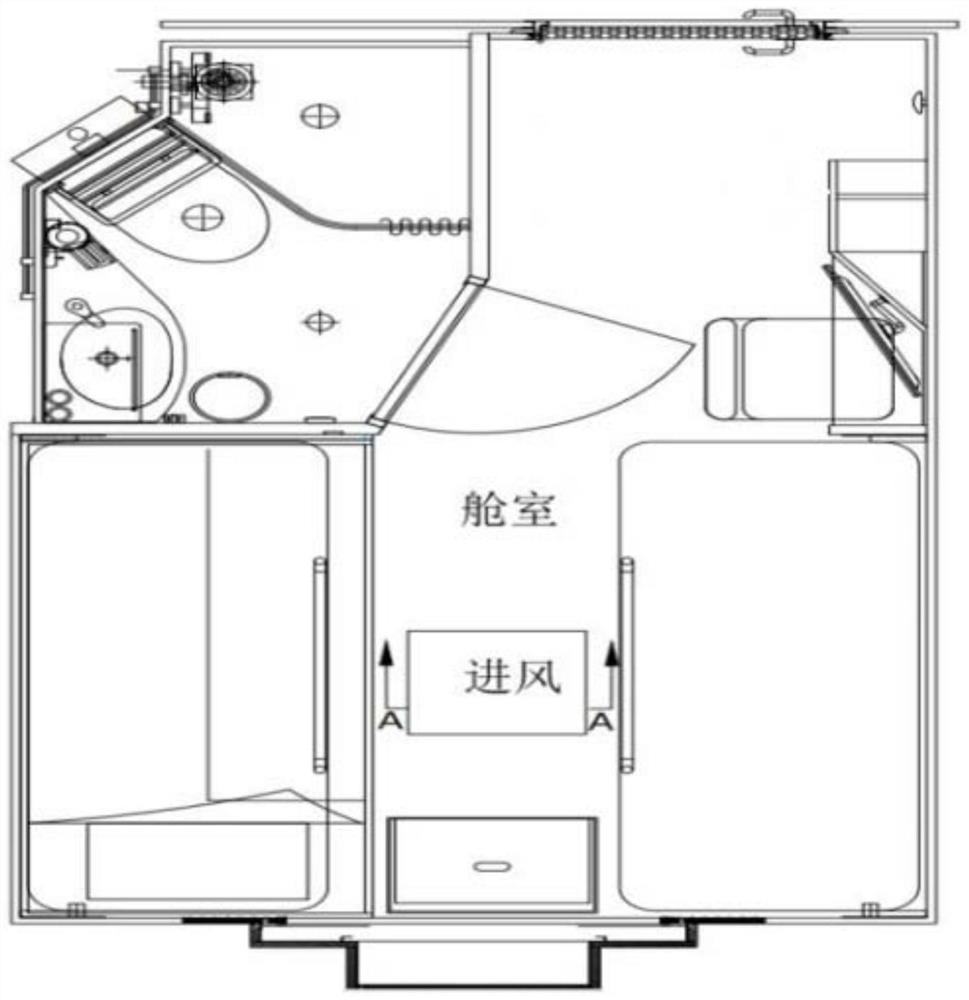
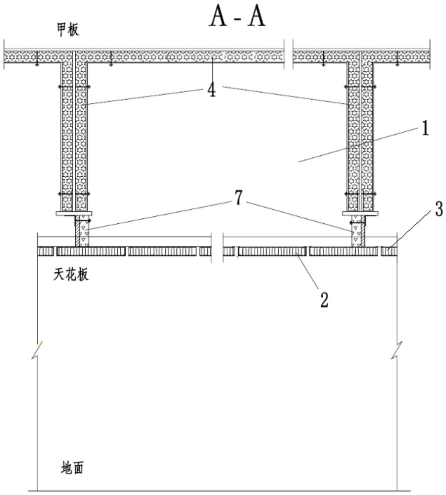
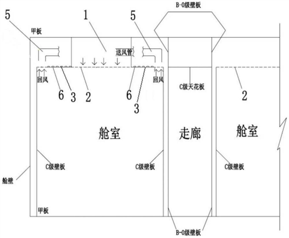

Image

  • Ship cabin rain falling type air supply and return system and ship
  • Ship cabin rain falling type air supply and return system and ship
  • Ship cabin rain falling type air supply and return system and ship

Examples


Embodiment Construction

[0034] In order to enable those skilled in the art to better understand the technical solutions of the present invention, the present invention will be described in detail below in conjunction with the accompanying drawings and specific embodiments.

[0035] Various aspects and features of the present application are described herein with reference to the accompanying drawings.

[0036] These and other characteristics of the present application will become apparent from the following description of preferred forms of embodiment given as non-limiting examples with reference to the accompanying drawings.

[0037] It should also be understood that, while the application has been described with reference to a few specific examples, those skilled in the art can certainly implement many other equivalents of the application, which have the features of the claims and are thus located. within the limited scope of protection.

[0038] The above and other aspects, features and advantage...


PUM


Abstract

The invention belongs to the field of ship ventilation and interior decoration, and provides a ship cabin rain-down type air supply and return system and a ship, and the system comprises a static pressure silencing box which is arranged below a deck of a ship cabin and is communicated with an air supply pipeline of the ship cabin; a first rain down ceiling which is arranged on the bottom face of the static pressure silencing box, and a first gap with the void ratio determined based on the air supply amount of the air conditioner is formed in the first rain down ceiling; and a second rain descending ceiling which communicates with an air return pipeline of the ship cabin, and a second gap with the void ratio determined based on the air return amount of the air conditioner is formed in the second rain descending ceiling; return air passes through the second rain down ceiling and then is sent back to the return air pipeline through the outside of the static pressure box silencing box. The air outlet area of the air conditioner is increased, air outlet of the air conditioner is uniform, the temperature field is good, and the air speed is reduced, so that noise reduction is achieved, and the comfort and experience of personnel in a cabin are improved; a grid does not need to be additionally arranged on a cabin door to serve as an air return opening, and privacy of personnel in a cabin is protected.

Description

technical field [0001] The invention belongs to the technical field of ship cabin ventilation and interior decoration, in particular to a ship cabin rain-drop air supply and return system and a ship. Background technique [0002] In order to provide a comfortable living environment for the crew or passengers on the ship, a balance of air-conditioning and fresh air needs to be achieved in the cabin: that is, the fresh air is sent into the cabin through the air conditioner on the ceiling, and a part of the air in the cabin also passes through the ceiling. The air conditioner returns to the outside of the cabin to achieve the balance of air volume and realize the circulation of air. How to set up a reasonable air supply and return path in the cabin without affecting the comfort of the cabin is a problem worth studying. [0003] As far as the existing cabin air supply path is concerned, the general ship is to install the air distributor on the ceiling and supply air through the...

Claims


Application Information

Patent Timeline
IPC IPC(8): B63J2/04
CPCB63J2/04
Inventor 谢飞陈大为张逸姚初晴于宁舟陈琛张新桥
Owner 中船邮轮科技发展有限公司
Why Eureka
Eureka Blog
Learn More