
Large-thickness separation structure without weakening groove, stress concentration or protective cover

A technology for separating structures and weakening grooves, which is applied in aerospace equipment, aerospace vehicles, docking devices of aerospace vehicles, etc., and can solve the requirements of inability to apply high-strength aluminum alloy shells, long production and inspection cycles, and neutrality High-level problems, to achieve the effect of shortening the development and production cycle, reducing the X-ray alignment inspection process, and convenient installation

Active Publication Date: 2021-10-22
BEIJING INST OF ASTRONAUTICAL SYST ENG
View PDF6 Cites 3 Cited by
  • Summary
  • Abstract
  • Description
  • Claims
  • Application Information

AI Technical Summary

Problems solved by technology

However, in recent years, advanced aerospace vehicles have become more and more demanding for high load-bearing structures. The load-bearing level is much higher than that of traditional flight loads, and the design thickness of the shell has been greatly increased, which is very unfavorable for the linear separation function, especially the realization of network cutting and separation.
The traditional network cutting separation structure uses detonating cord as the main separation power source, which cannot be applied to high-strength aluminum alloy shells with a thickness of more than 4mm. The protective cover is designed to suppress pressure for auxiliary cutting, and the concentrated load brought by the weakened groove under load-bearing conditions before the structure is separated has a significant impact on the load-bearing capacity of the structure, and the load-bearing capacity is greatly reduced
In addition, the pyrotechnic product of the traditional weakened tank separation device - the weakened tank has high requirements on neutrality, the process is complicated, and the production and inspection cycle is very long

Method used


Image

  • Large-thickness separation structure without weakening groove, stress concentration or protective cover
  • Large-thickness separation structure without weakening groove, stress concentration or protective cover
  • Large-thickness separation structure without weakening groove, stress concentration or protective cover

Examples


Embodiment Construction

[0026] The present invention will be further elaborated below in conjunction with embodiment.

[0027] Aiming at the shortcomings of the traditional line separation device, the present invention discloses a new network cutting and separation structure design scheme, which has the advantages of large thickness of the shell, no need to set weakening grooves, no stress concentration, and no protective cover, and can significantly improve the bearing capacity of the spacecraft separation structure. efficiency.

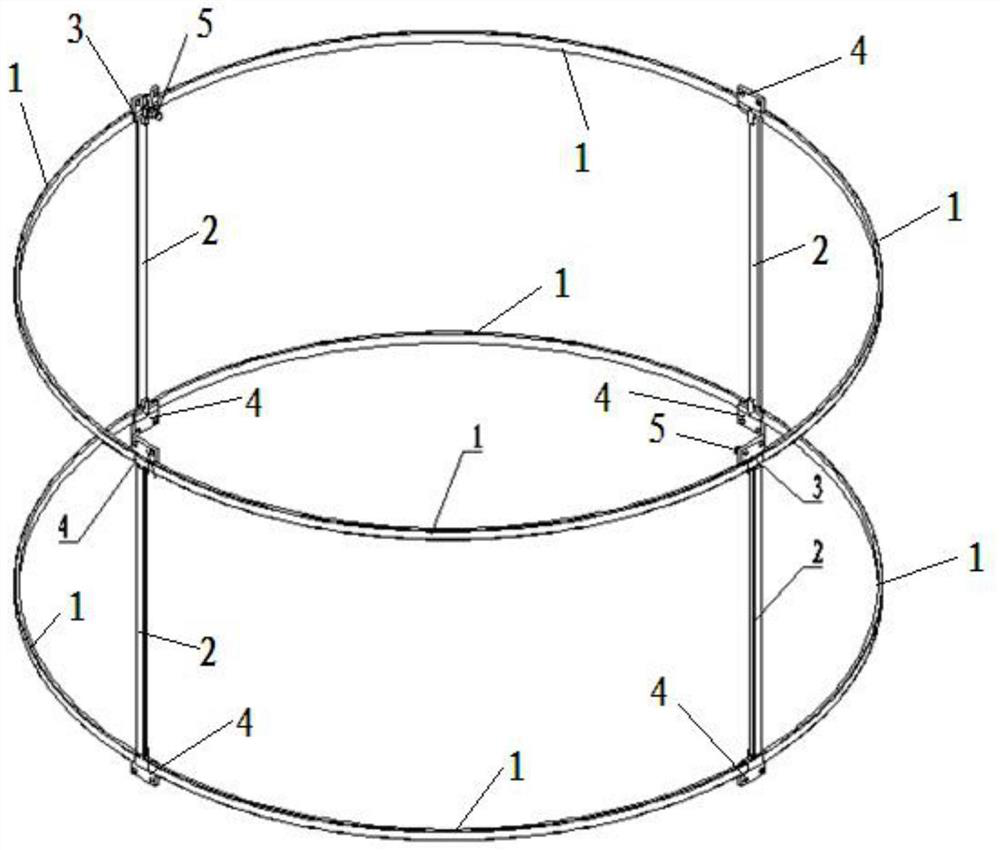
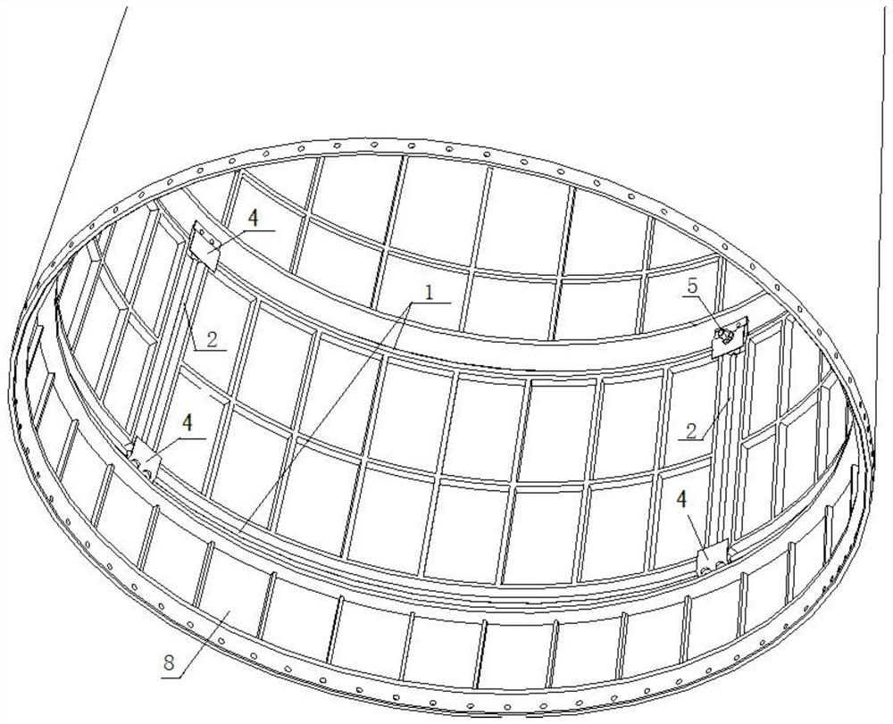
[0028] Large thickness, no weakening groove, no stress concentration, no protective cover separation structure, such as figure 1 As shown, it specifically includes 8 circumferential energy-shaping cutting cable assemblies 1, 4 longitudinal energy-shaping cutting cable assemblies 2, 2 four-way detonating assemblies 3, 6 three-way detonating assemblies 4 and 2 detonators 5; , every four ring-shaped energy-gathering cutting cable assemblies 1 are connected end-to-end to form...


PUM


Abstract

The invention relates to a large-thickness separation structure without a weakening groove, stress concentration or a protective cover, and belongs to the technical field of spacecraft structures. The structure comprises eight annular energy-gathered cutting rope assemblies, four longitudinal energy-gathered cutting rope assemblies, two four-way detonation assemblies, six three-way detonation propagation assemblies and two detonators. Every four annular energy-gathered cutting rope assemblies are sequentially connected end to end to form an annular structure. The four annular energy-gathered cutting rope assemblies located on the lower annular structure are connected through the four three-way explosion propagation assemblies. The four annular energy-gathered cutting rope assemblies located on the upper annular structure are connected through the two four-way detonating assemblies and the two three-way detonating propagation assemblies. The four longitudinal energy-gathered cutting rope assemblies are axially and vertically arranged between the two annular structures; each exploder is in butt joint communication with one four-way detonating assembly; transverse and longitudinal weakening grooves do not need to be formed, the stress concentration effect is avoided, and reliable structure separation is achieved without X-ray centering inspection and protection cover pressure building.

Description

technical field [0001] The invention belongs to the technical field of spacecraft structures, and relates to a large-thickness structure without weakening grooves, stress concentration, and protection cover separation. Background technique [0002] The main function of the line separation device in the aerospace vehicle is to quickly cut off the connection between the load-carrying shells when receiving the separation sequence order. Flexible detonating cord, energy-concentrated cutting cord, expansion tube-groove plate and other pyrotechnic separation devices have the advantages of avoiding concentrated connection load, light weight and reliable separation. However, in recent years, advanced aerospace vehicles have become more and more demanding for high load-bearing structures. The load-bearing level is much higher than that of traditional flight loads, and the design thickness of the shell has been greatly increased, which is very unfavorable for the linear separation fun...

Claims


Application Information

Patent Timeline
Patent Type & Authority Applications(China)
IPC IPC(8): B64G1/64
CPCB64G1/645
Inventor 闵昌万李岩吴锦涛汪锐琼赫志亮苏晗唐科郭永辉王群孙璟侯金瑛冯丽娜陈岱松陈楷李辰王筱宇张军
Owner BEIJING INST OF ASTRONAUTICAL SYST ENG
Learn More