A test load device for simulating battery cells
A technology for testing loads and batteries, applied in the detection field, can solve problems such as high cost, explosion, and inability to use real battery packs, and achieve the effects of facilitating testing, avoiding accidents, and reducing costs
- Summary
- Abstract
- Description
- Claims
- Application Information
AI Technical Summary
Problems solved by technology
Method used
Image
Examples
Embodiment 1
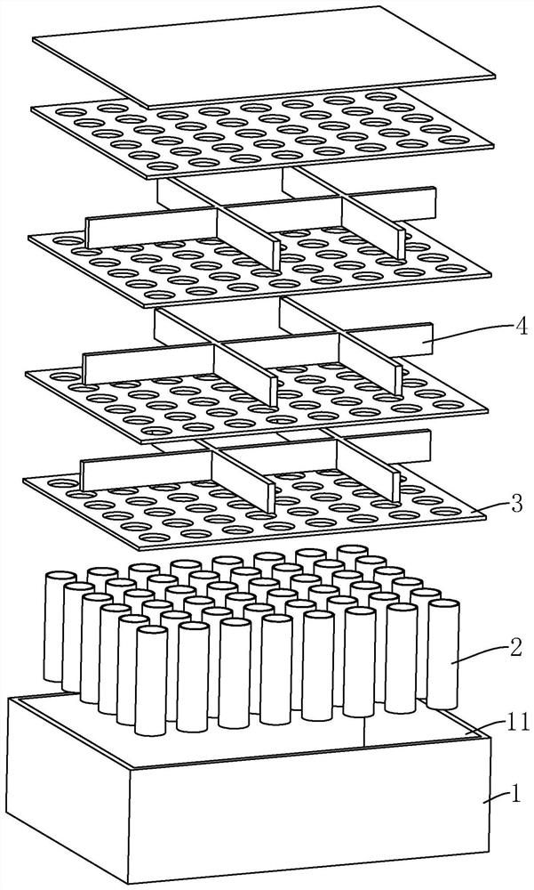
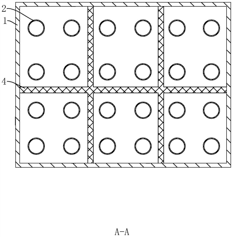
[0037] refer to figure 1 with figure 2 , a test load device for simulating a battery cell, comprising a housing 1, a housing chamber 11 is arranged in the housing 1, a supporting unit is arranged in the housing chamber 11, the supporting unit is connected to the side wall of the housing 1, the supporting unit and The casing 1 constitutes a test load device for simulating the battery cell for testing to test its resistance to pressure and deformation. The placement direction of the casing 1 during the test is defined as the up-down direction, and the corresponding supporting units are arranged along the up-down direction.
[0038] refer to figure 1 with figure 2 , in this embodiment, the housing 1 is a closed structure, the housing 1 is composed of a bottom plate, a top plate and a side plate, the side plate is bent to form a structure with a back-shaped cross section, and the bottom plate, the top plate and the side plate are surrounded to form an accommodating cavity 11,...
Embodiment 2
[0044] The difference from Embodiment 1 is that the arrangement of the multiple support tubes 2 is different, with one of the support tubes 2 as the center, and the other support tubes 2 are circumferentially distributed outside the central support tube 2 .
Embodiment 3
[0046] The difference from Embodiment 1 is that the structure of the second positioning unit is different. The second positioning unit includes a first positioning ring 5 and a plurality of third positioning plates 6, and the plurality of third positioning plates 6 are uniformly connected to the first positioning ring in the circumferential direction. The outer wall of a positioning ring 5, the first positioning ring 5 and a plurality of third positioning plates 6 are located between the adjacent first positioning plates 3, wherein the support tube 2 near the center passes through the first positioning ring 5, and the corresponding support The tubes 2 are located between adjacent third positioning plates 6 .
PUM
 Abstract
Description
Claims
Application Information
 - R&D
- Intellectual Property
- Life Sciences
- Materials
- Tech Scout
- Unparalleled Data Quality
- Higher Quality Content
- 60% Fewer Hallucinations
Browse by: Latest US Patents, China's latest patents, Technical Efficacy Thesaurus, Application Domain, Technology Topic, Popular Technical Reports.
© 2025 PatSnap. All rights reserved.Legal|Privacy policy|Modern Slavery Act Transparency Statement|Sitemap|About US| Contact US: help@patsnap.com


