
Redis multi-instance monitoring system and method

A monitoring system and multi-instance technology, applied in the transmission system, digital transmission system, electrical components, etc., can solve the problems of slow project implementation speed, no visual monitoring interface, and low performance index processing performance, so as to reduce maintenance costs and learn cost, improve system horizontal scalability, and reduce product coupling effects

Active Publication Date: 2021-10-22
BANK OF CHINA
View PDF9 Cites 5 Cited by
  • Summary
  • Abstract
  • Description
  • Claims
  • Application Information

AI Technical Summary

Problems solved by technology

[0002]At present, most monitoring systems use technical architectures based on Nagios or Zabbix frameworks. These technical frameworks often have problems such as complex configuration, poor flexibility, and low efficiency; for example, Nagios: There is no self-discovery function, and the configuration file needs to be frequently modified; the configuration is limited to the terminal, and the scalability is poor; the performance index processing performance is low; there is no historical data, and it is difficult to trace faults, etc.
Zabbix: There is an obvious performance bottleneck; the cost is high, and the bottleneck problem of database writing needs to be solved by adding a proxy, and the efficiency is low; the use requires secondary development, which increases personnel costs and reduces the speed of project implementation. The built-in housekeeping will continue to produce database during execution. increase pressure
[0003] In summary, there is an urgent need for a Redis multi-instance monitoring technology solution that can overcome the above defects, and solve the problems of poor scalability, low performance, and difficult traceability in existing systems Historical data, there are technical problems such as performance bottlenecks, high cost of use, and no visual monitoring interface

Method used


Image

  • Redis multi-instance monitoring system and method
  • Redis multi-instance monitoring system and method
  • Redis multi-instance monitoring system and method

Examples


Embodiment Construction

[0045] The principle and spirit of the present invention will be described below with reference to several exemplary embodiments. It should be understood that these embodiments are given only to enable those skilled in the art to better understand and implement the present invention, rather than to limit the scope of the present invention in any way. Rather, these embodiments are provided so that this disclosure will be thorough and complete, and will fully convey the scope of the disclosure to those skilled in the art.

[0046] Those skilled in the art know that the embodiments of the present invention can be implemented as a system, device, device, method or computer program product. Therefore, the present disclosure may be embodied in the form of complete hardware, complete software (including firmware, resident software, microcode, etc.), or a combination of hardware and software.

[0047]According to an embodiment of the present invention, a Redis multi-instance monitori...


PUM


Abstract

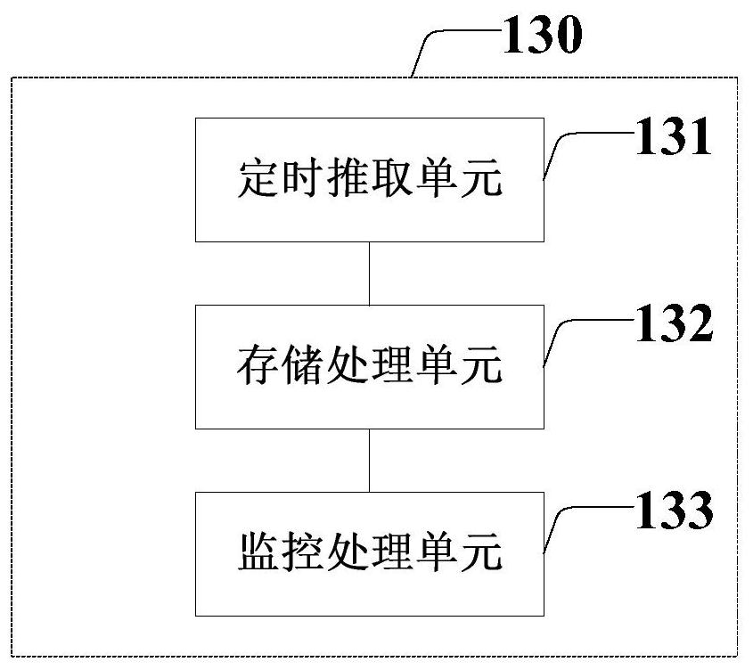
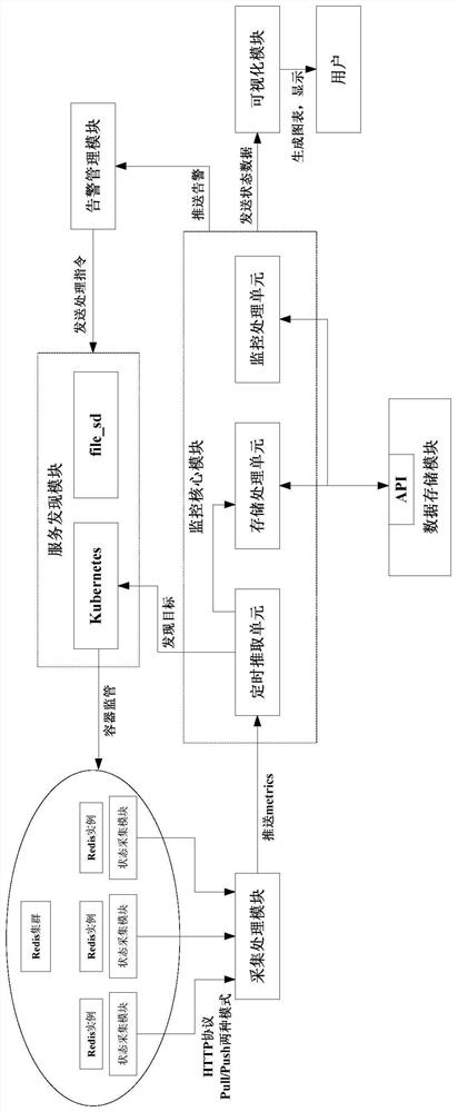
The invention provides a Redis multi-instance monitoring system and method, and relates to the technical field of cluster operation state monitoring, and the system comprises a state acquisition module which is integrated in Redis instances and is used for acquiring performance indexes; an acquisition mode processing module which is used for adjusting the mode of the state acquisition module according to different monitoring scenes; a monitoring core module which is used for calling a performance index, performing state analysis and alarm analysis according to a configured monitoring rule, and generating a state analysis result and alarm information; a data storage module which is used for data persistence; an alarm management module which is used for acquiring alarm information, generating a state adjustment instruction according to the alarm information, and driving a service discovery module to process an abnormal node in a Redis container; the service discovery module which is used for monitoring a container environment where the Redis instance is located and performing operation and maintenance management on nodes of the Redis container; and a visualization module which is used for displaying a monitoring data report through a visualization interface.

Description

technical field [0001] The invention relates to the technical field of cluster operation status monitoring, in particular to a Redis multi-instance monitoring system and method. Background technique [0002] At present, the monitoring system mostly adopts the technical architecture based on Nagios or Zabbix framework, and these technical frameworks often have problems such as complex configuration, poor flexibility, and low efficiency; for example, Nagios: there is no self-discovery function, and configuration files need to be frequently modified; configuration is limited to Terminal, poor scalability; low performance index processing performance; no historical data, difficult to trace faults and other issues. Zabbix: There is an obvious performance bottleneck; the cost is high, and the bottleneck problem of database writing needs to be solved by adding a proxy, and the efficiency is low; the use requires secondary development, which increases personnel costs and reduces the...

Claims


Application Information

Patent Timeline
IPC IPC(8): H04L12/26H04L12/24
CPCH04L43/045H04L41/0631H04L41/22
Inventor 郭赫
Owner BANK OF CHINA
Learn More