Temperature control earmuff and temperature control earphone thereof

An earmuff and cover body technology, applied in the field of temperature-controlled earmuffs and temperature-controlled earphones, can solve the problems of ear damage, affecting user comfort, noise heat transfer efficiency, etc. Poor usability and improved heat transfer efficiency

Pending Publication Date: 2021-10-22
深圳实益达电声有限公司
View PDF0 Cites 0 Cited by
  • Summary
  • Abstract
  • Description
  • Claims
  • Application Information

AI Technical Summary

Problems solved by technology

[0003] However, when worn for a long time or in hot weather, due to the good airtightness between the auricle and the earmuffs, it is easy to cause heat and sweat in the auricle, which affects the comfort of the user and may cause damage to the ear. cause harm
[0004] In the cold winter, the ears are more susceptible to the impact of low temperature. The earphones have no temperature control, and the experience in low temperature is poor.
[0005] At present, semiconductor cooling chips are mainly installed in the earmuffs of the earphones to adjust the temperature of the earmuffs. When the current passes through the semiconductor cooling chips, heat transfer will occur at both ends of the semiconductor cooling chips, thereby forming a hot end and a cold end, and changing the current. The direction of the direction will change the position of the hot end and the cold end. Therefore, the earmuffs using the semiconductor cooling sheet have the function of adjusting the temperature. However, in the semiconductor cooling sheet, when the temperature difference between the hot end and the cold end reaches a certain value, the heat transfer point At the balance point, the temperature of the hot and cold ends no longer changes, and when the temperature of the cold end needs to be reduced, the heat dissipation of the hot end needs to be strengthened
[0006] At present, the heat dissipation methods of the hot end include natural heat dissipation, liquid flushing heat dissipation, vacuum latent heat dissipation, and strong wind heat dissipation. Among them, natural heat dissipation requires a large heat dissipation area and is not suitable for use on earmuffs, and liquid flushing heat dissipation requires the use of liquid and provides liquid circulation. The power device will have the risk of damaging the earmuffs and is more troublesome to use. The strong wind cooling method requires a fan, which will generate a lot of noise and affect the sense of use. The vacuum latent heat cooling method requires more heat pipes. The heat dissipation efficiency is not ideal. Therefore, it is necessary to provide a temperature-controlled earphone with a suitable heat dissipation structure to solve the technical problems that the temperature-controlled earphone will cause heat and sweat in the ear, resulting in poor sense of use, noise and low heat transfer efficiency. , providing a temperature-controlled earphone including temperature-controlled earmuffs

Method used


Image

  • Temperature control earmuff and temperature control earphone thereof
  • Temperature control earmuff and temperature control earphone thereof
  • Temperature control earmuff and temperature control earphone thereof

Examples


Embodiment Construction

[0034] The following will clearly and completely describe the technical solutions in the embodiments of the present invention with reference to the accompanying drawings in the embodiments of the present invention. Obviously, the described embodiments are only part of the embodiments of the present invention, not all of them. Based on the embodiments of the present invention, all other embodiments obtained by persons of ordinary skill in the art without creative efforts fall within the protection scope of the present invention.

[0035] It should be noted that all directional indications (such as up, down, left, right, front, back...) in the embodiments of the present invention are only used to explain the relationship between the components in a certain posture (as shown in the accompanying drawings). Relative positional relationship, movement conditions, etc., if the specific posture changes, the directional indication will also change accordingly.

[0036] In addition, the ...


PUM


Abstract

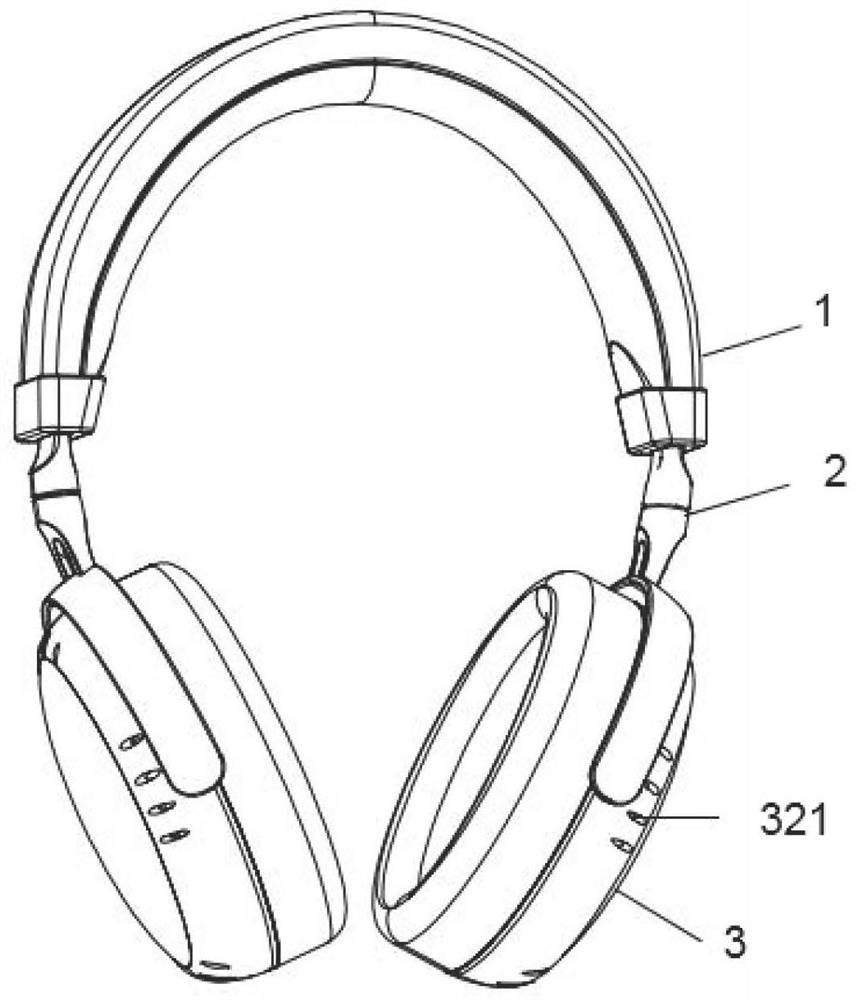
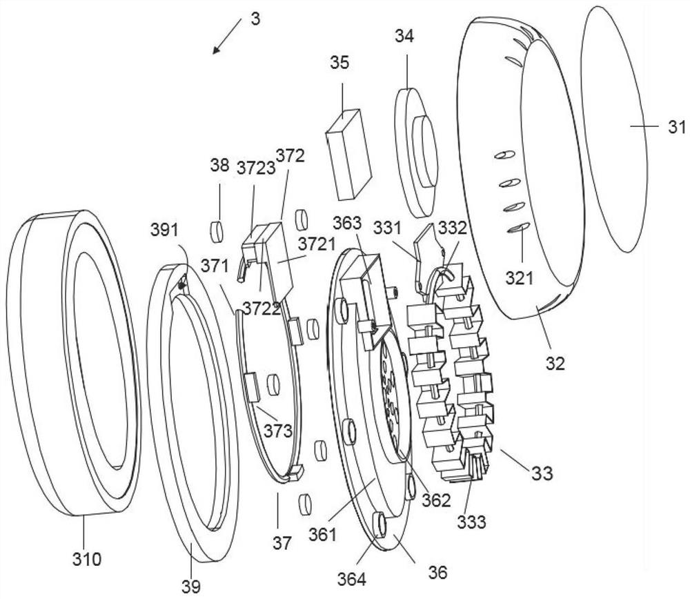
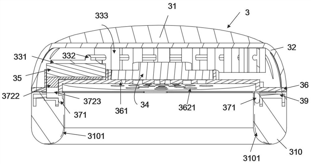
A temperature control earmuff comprises a muff body and an earmuff. A thermal insulation horn seat is clamped in the muff body, a horn heat conduction piece is arranged on an inner ring of the thermal insulation horn seat, and the temperature control earmuff is characterized in that a sound production assembly and a semiconductor chilling plate are connected to the side face, away from the earmuff, of the horn heat conduction piece, and the temperature control earmuff further comprises a heat dissipation assembly; the heat dissipation assembly comprises a first annular heat conduction piece, a heat conduction piece and a plurality of heat dissipation pieces, the heat dissipation pieces are arranged on the first annular heat conduction piece, one side face of the heat conduction piece is used for being connected with the first annular heat conduction piece, and the other side face of the heat conduction piece is tightly attached to the heating face of the semiconductor chilling plate. The heat dissipation assembly and the horn heat conduction piece are arranged in a non-contact mode, the earmuff comprises a heat conduction structure, the refrigeration face of the semiconductor refrigeration piece transmits a cold source to the horn heat conduction piece and the heat conduction structure to achieve refrigeration of the inner side of the earmuff, and the temperature control earphone has the functions of being free of noise, high in heat transfer rate and free of heating and sweating in the ear.

Description

technical field [0001] The invention relates to the technical field of headphones, in particular to a temperature-controlled earmuff and a temperature-controlled earphone. Background technique [0002] The earphones have sponge as a sealed and sound-proof earmuff, which can better isolate interference and have a better sound experience. [0003] However, when worn for a long time or in hot weather, due to the good airtightness between the auricle and the earmuffs, it is easy to cause heat and sweat in the auricle, which affects the comfort of the user and may cause damage to the ear. cause harm. [0004] In the cold winter, the ears are more susceptible to the impact of low temperature. The earphones have no temperature control, and the experience in low temperature is poor. [0005] At present, semiconductor cooling chips are mainly installed in the earmuffs of the earphones to adjust the temperature of the earmuffs. When the current passes through the semiconductor cooli...

Claims


Application Information

Patent Timeline
Patent Type & Authority Applications(China)
IPC IPC(8): H04R1/10H05K5/02H05K7/20
CPCH04R1/1008H04R1/1091H04R1/1083H05K7/20336H05K7/2039H05K5/0213H04R1/1058
Inventor 陈纯瑜李先旭邱正军
Owner 深圳实益达电声有限公司
Why Eureka
Try Eureka