A collection device based on environmental protection chemical fiber silk scraps

A collection device and a technology of chemical fiber yarn, which is applied in the field of collection devices based on environmental protection chemical fiber yarn scraps, can solve the problems of low efficiency of chemical fiber scraps, and achieve the effect of improving convenience and collection efficiency

Active Publication Date: 2022-04-29
罗慧嘉
View PDF8 Cites 0 Cited by
  • Summary
  • Abstract
  • Description
  • Claims
  • Application Information

AI Technical Summary

Problems solved by technology

[0004] In order to overcome the disadvantages of large size, harsh use environment and low efficiency of collecting chemical fiber leftovers, the technical problem to be solved is to provide a small size that is suitable for most environments and has low collection efficiency for chemical fiber leftovers. Higher collection device based on environmental protection chemical fiber scraps

Method used


Image

  • A collection device based on environmental protection chemical fiber silk scraps
  • A collection device based on environmental protection chemical fiber silk scraps
  • A collection device based on environmental protection chemical fiber silk scraps

Examples


Embodiment 1

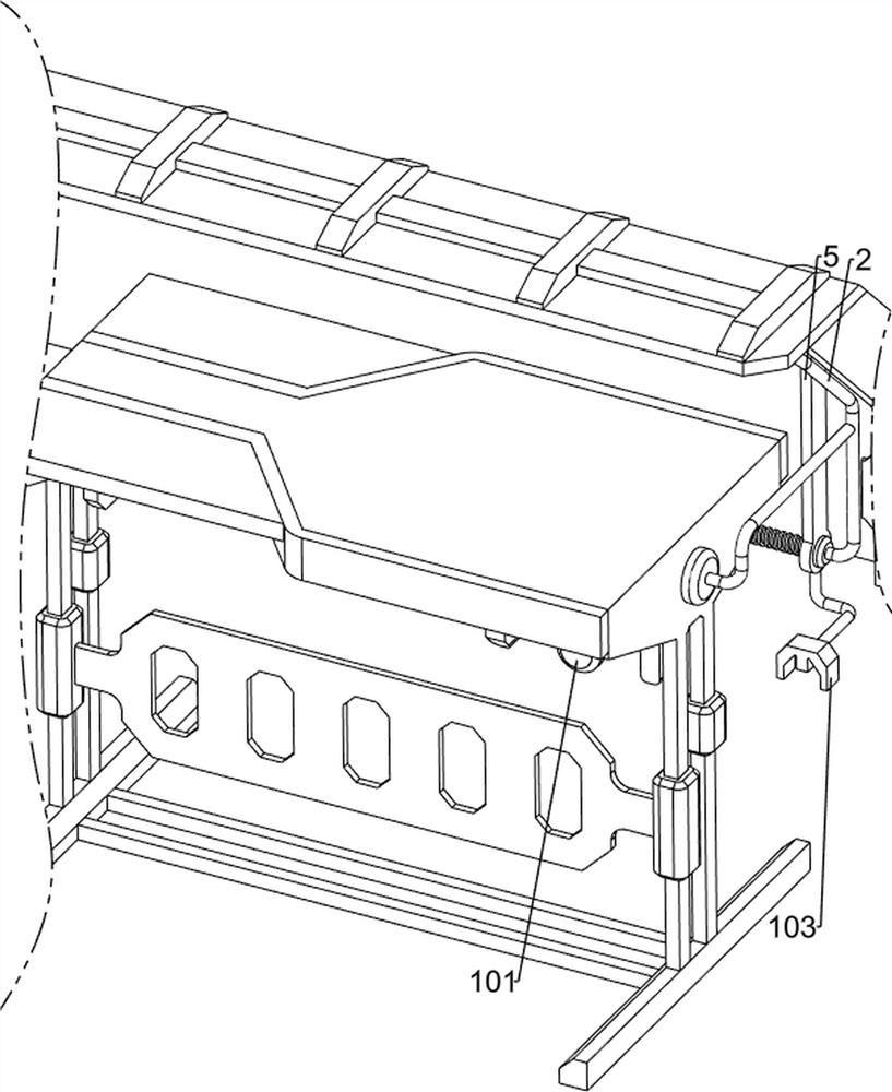
[0073] A kind of collection device based on environmental protection chemical fiber silk leftovers, such as Figure 1-Figure 3 As shown, it includes a first support frame 1, a second support frame 2, a first baffle plate 3, a screw mandrel 4, a first movable plate 5, a motor 6, a third support frame 7, a clamping mechanism 8 and a collection mechanism 9 , the upper part of the first support frame 1 is provided with the second support frame 2, the upper part of the second support frame 2 is provided with the first baffle plate 3, the rear side lower part of the second support frame 2 is rotatably provided with a screw rod 4, and the screw rod 4 is threaded The formula is provided with a first movable plate 5, the first movable plate 5 is slidably connected with the second support frame 2, the left side of the second support frame 2 is provided with a third support frame 7, and a motor 6 is installed on the bottom of the third support frame 7, The output shaft of the motor 6 is ...

Embodiment 2

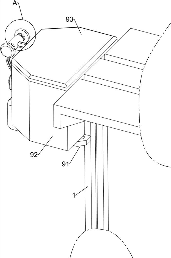
[0076] In a preferred embodiment of the present invention, as Figure 4-Figure 6 As shown, the clamping mechanism 8 includes a fourth support frame 81, a first slide rail 82, a splint 83, a first spring 84 and a material brush 85, and a fourth support frame 81 is provided on the front side of the upper part of the first movable plate 5. The bottom of the four supporting frame 81 is provided with a first slide rail 82, and two splints 83 are slidably arranged on the first slide rail 82. The left and right sides of the first slide rail 82 are equipped with a first spring 84, and the first spring 84 inner end Connected to the splint 83 , the outer end of the first spring 84 is connected to the fourth support frame 81 , and a material brush 85 is installed between the two splints 83 .

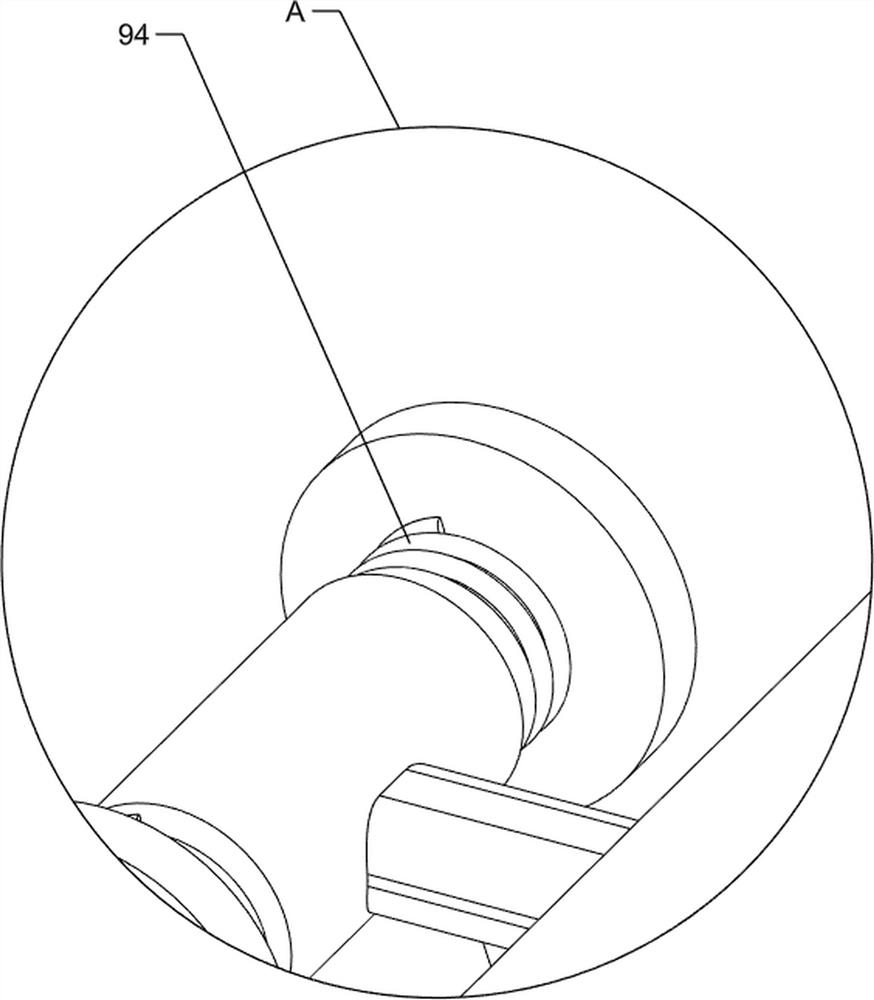
[0077] When people start the motor 6, the movement of the first movable plate 5 to the left can drive the fourth support frame 81 to move to the left, and then can drive the first slide rail 82 to ...

Embodiment 3

[0081] In a preferred embodiment of the present invention, as figure 1 , figure 2 with Figure 7-Figure 14 As shown, a material guide mechanism 10 is also included, and the material guide mechanism 10 includes a sixth support frame 101, a first movable block 102, a first wedge block 103 and a second movable plate 104, and the first support frame 1 top is provided with a second Six bracing frames 101, the sixth bracing frame 101 bottom is rotatably provided with the first movable block 102, the first movable plate 5 bottom is provided with the first wedge-shaped block 103, the first wedge-shaped block 103 cooperates with the first movable block 102, the first The upper part of the support frame 1 is slidably provided with a second movable plate 104 , and the second movable plate 104 cooperates with the first movable block 102 .

[0082] When the first movable plate 5 moved to the left, the first movable plate 5 could drive the first wedge block 103 to move to the left, and w...


PUM


Abstract

The invention relates to a collecting device, in particular to a collecting device based on environment-friendly chemical fiber leftovers. The invention provides an environment-friendly chemical fiber leftover collection device which is small in size, applicable to most environments, and has high efficiency in collecting chemical fiber leftovers. The present invention provides such a collection device based on environment-friendly chemical fiber silk leftovers, comprising: a second support frame, a second support frame is provided on the upper part of the first support frame; a first baffle plate, a first baffle is provided on the upper part of the second support frame plate; screw rod, the second support frame is provided with a screw rod for rotation; the first movable plate is threadedly provided with a first movable plate, and the first movable plate is slidably connected with the second support frame. The invention cooperates with the collecting mechanism through the clamping mechanism, the clamping mechanism can clean the leftovers of chemical fibers, and the collecting mechanism can collect the leftovers of chemical fibers, thereby improving the collection efficiency of the leftovers of chemical fibers.

Description

technical field [0001] The invention relates to a collecting device, in particular to a collecting device based on environment-friendly chemical fiber leftovers. Background technique [0002] Chemical fiber filament is a kind of fiber with textile properties made from natural polymer compounds or artificially synthesized polymer compounds through the processes of preparing spinning dope, spinning and post-treatment. The mechanical properties of this fiber are stable. , and have good tensile and water immersion resistance properties. Due to the better performance of chemical fiber filaments, the use of chemical fiber filaments is becoming wider and wider, so the production volume of chemical fiber filaments is also increasing. A large number of The production of chemical fiber filaments will cause a certain consumption of material resources. Therefore, in order to protect the environment, people began to collect and recycle the scraps of chemical fiber filaments after use. Ho...

Claims


Application Information

Patent Timeline
Patent Type & Authority Patents(China)
IPC IPC(8): B08B1/00B08B13/00
CPCB08B1/002B08B1/008B08B13/00
Inventor 罗慧嘉
Owner 罗慧嘉
Why Eureka
Try Eureka