Manufacturing method of outer ring splicing block assembly

A manufacturing method and technology of block components, applied in the direction of manufacturing tools, metal processing machinery parts, clamping, etc., can solve problems such as processing errors, surface misalignment, large gaps in joint surfaces, etc., to improve processing efficiency, improve overall accuracy, The effect of improving the pass rate

Pending Publication Date: 2021-10-26
SHENYANG LIMING AERO-ENGINE GROUP CORPORATION
View PDF5 Cites 2 Cited by
  • Summary
  • Abstract
  • Description
  • Claims
  • Application Information

AI Technical Summary

Problems solved by technology

[0003] The traditional processing method is to process each block individually by CNC, but even if it relies on high-precision CNC machine tools, there will be processing errors. Due to the accumulation of errors during assembly, the shape of each block will be dislocated. When placing a piece, it often happens that the last piece cannot be put in or there is a large gap on the joint surface, which is caused by the accumulation of the joint surface errors of all the pieces.
The traditional solution is to rely on the fitter for manual correction and smooth transfer, but manual correction is random and accidental, which will cause the overall accuracy of the outer ring to drop to 0.3-0.5mm; for this reason, the present invention provides an outer ring Method of making ring block assembly

Method used


Image

  • Manufacturing method of outer ring splicing block assembly
  • Manufacturing method of outer ring splicing block assembly
  • Manufacturing method of outer ring splicing block assembly

Examples


Embodiment Construction

[0032] The present invention will be further described in detail below in conjunction with the accompanying drawings and embodiments.

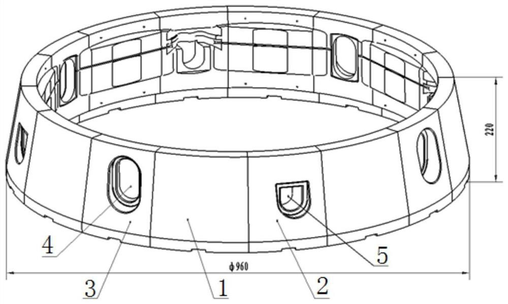
[0033] A method for manufacturing an outer ring block assembly, comprising the following steps:

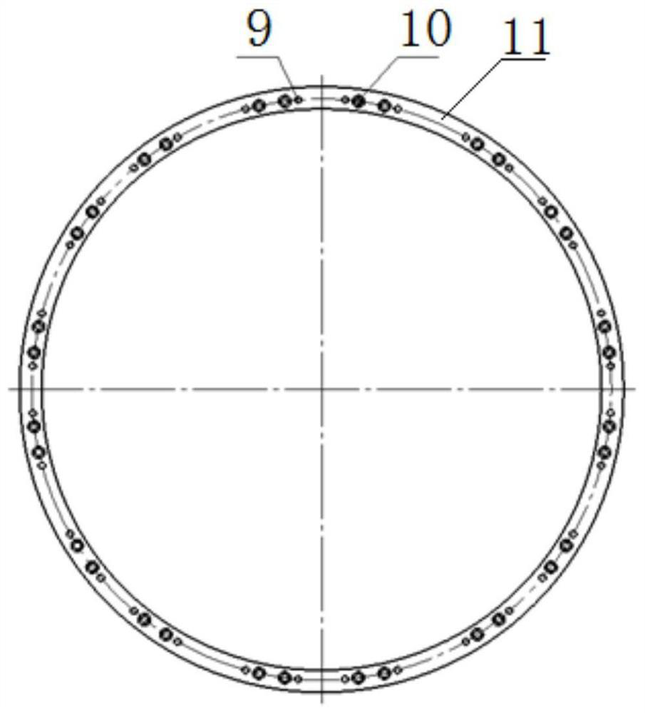
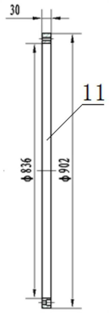
[0034] Step 1, such as Figure 2-Figure 5 As shown, the jig plate is made, and the jig plate annular plate is divided into two types: the A-side jig plate 11 and the B-side jig plate 12, and the outer diameter of the B-side jig plate 12 is larger than the outer diameter of the A-side jig plate 11, respectively. Pin holes 9 and screw holes 10 are bored out on the plate 11 and the fixture plate 12 on the B side. The purpose of the fixture plate 11 on the A side and the fixture plate 12 on the B side is to be fixed on the A side 6 of the piece I1, the piece II2 and the piece III3. and on the B side 7, so that each piece is connected and fixed into a whole ring;

[0035] Step 2, such as Figure 6-Figure 11 As shown, each piece is blanked into a cub...


PUM


Abstract

The invention discloses a manufacturing method of an outer ring splicing block assembly. The manufacturing method comprises the following steps that S1, clamp plates are manufactured; S2, the joint faces of splicing blocks I, splicing blocks II and splicing blocks III are machined to the size, positioning pin holes are bored in the faces A and the faces B of the splicing blocks I, and threaded holes are machined in the faces A and the faces B of the splicing blocks I; S3, the splicing blocks I are assembled on the clamp plate, then the splicing blocks II and the splicing blocks III are assembled between the two splicing blocks I by sequentially grinding the joint surfaces, then pin holes and screw holes are drilled in the splicing blocks II and the splicing blocks III through the pin holes and the screw holes of the clamp plate respectively, and the splicing blocks and the clamp plate are fixed; S4, an outer surface, an inner molded surface, molded holes I and molded holes II are machined; S5, the inner molded surface, the outer surface, the molded holes I and the molded holes II are integrally detected; and S6, marks are detected, the A-face clamp plate and the B-face clamp plate are detached, and machining is completed. According to the manufacturing method, dislocation and out-of-tolerance of the overall molded surface caused by error accumulation during single piece machining can be avoided, and the overall precision after the outer ring splicing blocks are combined can be improved.

Description

technical field [0001] The invention belongs to the technical field of mechanical processing of block assemblies in mold processing, and in particular relates to a manufacturing method of an outer ring block assembly. Background technique [0002] In mold manufacturing, components composed of multiple blocks are often encountered, and the outer ring block component is one of them, such as figure 1 shown. The characteristics of the outer ring block assembly are: the assembly is surrounded by 8 pieces of block I, 4 pieces of block II, and 4 pieces of block III to form a ring. With 8 holes. After assembly, the internal and external profiles are required to be consistent, and no misalignment can occur. The dimensional tolerance after assembly is required to reach 0.05mm, and the fit gap between the pieces must not exceed 0.03mm. [0003] The traditional processing method is to process each block individually by CNC, but even if it relies on high-precision CNC machine tools, t...

Claims


Application Information

Patent Timeline
Patent Type & Authority Applications(China)
IPC IPC(8): B23P15/00B23Q3/06B23Q17/20
CPCB23P15/00B23Q3/06B23Q17/20
Inventor 王培伟杨树龙李准韩硕
Owner SHENYANG LIMING AERO-ENGINE GROUP CORPORATION
Why Eureka
Try Eureka