Feeding device for sanitation truck garbage can

A technology of trash cans and sanitation vehicles, which is applied in the field of trash can loading, can solve the problems of long garbage can easily spill outside the collection bucket, the service life of the trash can is reduced, and the shell of the trash can is greatly worn, so as to improve the feeding efficiency, The effect of pouring thoroughly and reducing friction

Inactive Publication Date: 2021-10-26
马宁
View PDF0 Cites 0 Cited by
  • Summary
  • Abstract
  • Description
  • Claims
  • Application Information

AI Technical Summary

Problems solved by technology

However, in order to ensure the stability and fixation of the trash can, a clamping force far greater than the gravity of the trash can is often applied to the trash can, resulting in greater wear and tear on the shell of the trash can during each loading process of the trash can, resulting in the use of the trash can The service life is greatly reduced, and during the process of dumping garbage, the garbage is easy to spill outside the collection bucket for a long time, causing secondary pollution. After the dumping is completed, more garbage remains inside the trash can, resulting in incomplete dumping

Method used


Image

  • Feeding device for sanitation truck garbage can
  • Feeding device for sanitation truck garbage can
  • Feeding device for sanitation truck garbage can

Examples


Embodiment Construction

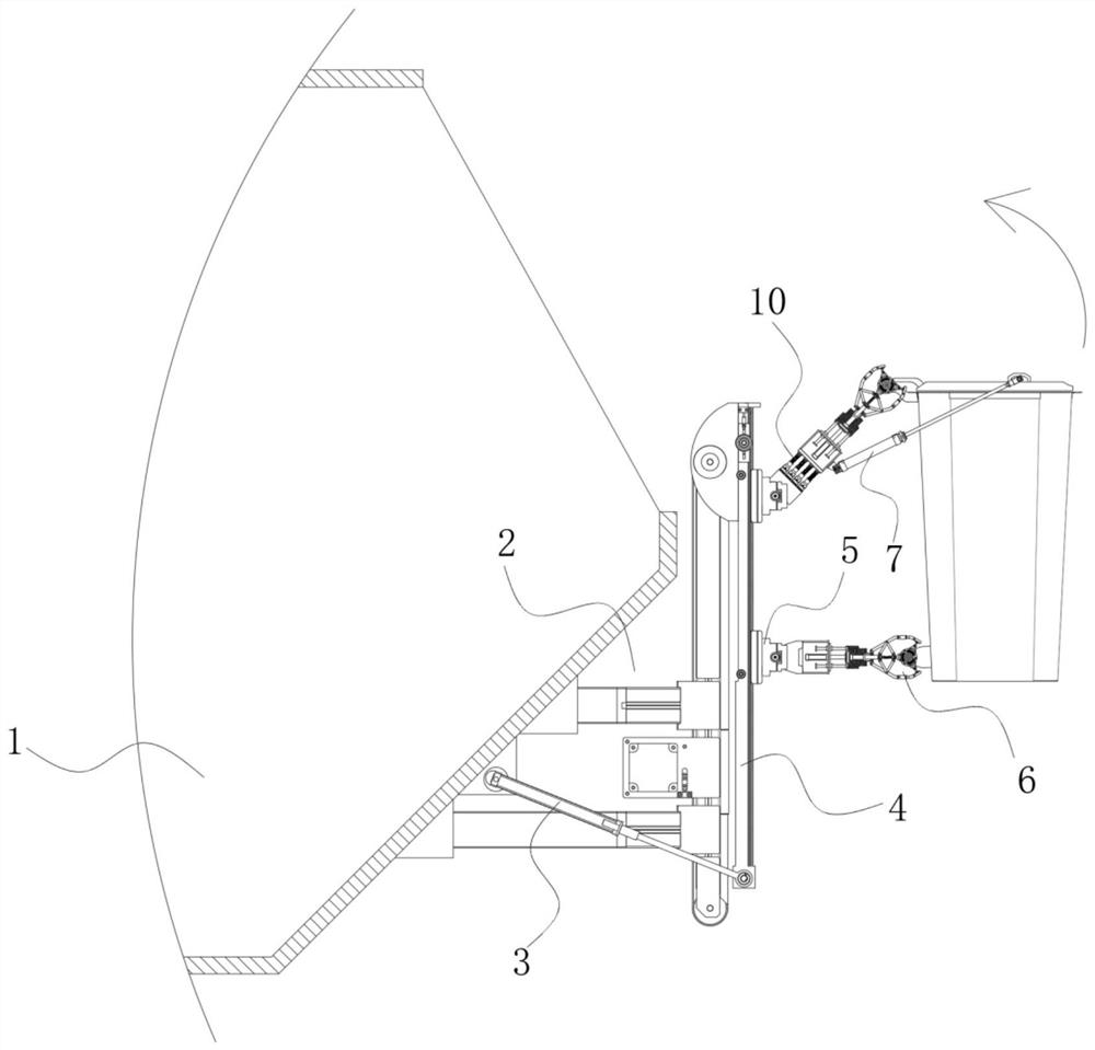
[0043] refer to figure 1 , the present invention provides a technical solution: a garbage bin feeding device for sanitation vehicles, which includes:

[0044] The rotary driving device 2 is installed on the inclined shell wall on the right side of the sanitation collection bucket 1, and its driving structure is arranged longitudinally;

[0045] Lifting frames 4, at least two groups, are arranged in parallel front and back, the upper end of which is hinged with the output end of the rotary drive device 2 through the rotating seat, so as to improve the supporting strength of the trash can and the stability during the feeding process;

[0046] The telescopic rod-3, at least two groups, is symmetrically hinged on the front and rear sides of the inclined shell wall on the right side of the sanitation collection bucket 1, and its output end is hinged to the lower end of the lifting frame 4, further, it assists the loading of the trash can and reduces the impact on the rotating drive...


PUM


Abstract

The invention discloses a feeding device for a sanitation truck garbage can. The feeding device comprises a rotation driving device, at least two groups of lifting frames, at least two groups of first telescopic rods, two groups of lifting seats and clamping devices. The rotation driving device is installed on the right side inclined shell wall of a sanitation collecting hopper, and a driving structure of the rotation driving device is longitudinally arranged; the lifting frames are arranged in parallel front and back, and the upper ends of the lifting frames are hinged to the output end of the rotary driving device through rotating seats; the first telescopic rods are symmetrically hinged to the front side and the rear side of the right inclined shell wall of the sanitation collecting hopper, and the output ends of the first telescopic rods are hinged to the lower ends of the lifting frames; the lifting seats are arranged up and down and installed on the lifting frames, the number of the lifting seats is equal to the number of the lifting seats installed on one set of lifting frame, and positioning rotating seats and oscillators are hinged to the lifting seats on the lower portion and the upper portion of the lifting frames correspondingly; and the clamping devices are arranged corresponding to the lifting seats, and the lower clamping device and the upper clamping device are fixed to the positioning rotating seats and the oscillators respectively.

Description

technical field [0001] The invention relates to the technical field of garbage can loading, in particular to a garbage can loading device for sanitation vehicles. Background technique [0002] In the existing sanitation vehicle garbage can loading device, most of them adopt mechanical transmission to hang the garbage can for feeding. However, in order to ensure the stability and fixation of the trash can, a clamping force far greater than the gravity of the trash can is often applied to the trash can, resulting in greater wear and tear on the shell of the trash can during each loading process of the trash can, resulting in the use of the trash can The service life is greatly reduced, and during the process of dumping the garbage, the garbage is easy to spill out of the collection bucket for a long time, causing secondary pollution. [0003] Therefore, those skilled in the art provide a garbage bin loading device for sanitation vehicles to solve the problems raised in the ab...

Claims


Application Information

Patent Timeline
Patent Type & Authority Applications(China)
IPC IPC(8): B65F3/02
CPCB65F3/02B65F2003/023B65F2003/0223B65F2003/025B65F2003/0266B65F2003/0289B65F2003/0296
Inventor 李长明侯爱松马宁
Owner 马宁
Why Eureka
Try Eureka