Shield tunneling machine cutterhead capable of conveniently adjusting cutter distance

A technology of shield machine and cutter distance, which is applied in the direction of earth drilling, mining equipment, mining equipment, etc. It can solve the problems of difficult cutter disassembly and low work efficiency, and achieve the effect of improving work efficiency and stability

Inactive Publication Date: 2021-10-26
张宇
View PDF0 Cites 0 Cited by
  • Summary
  • Abstract
  • Description
  • Claims
  • Application Information

AI Technical Summary

Problems solved by technology

[0002] In our country, it is customary to call the tunnel boring machine used in soft soil strata a shield machine, and the tunnel boring machine used in a rock stratum as a full-section tunnel boring machine. The basic working principle of shield tunneling method construction is a cylindrical steel component The soil is excavated while pushing forward along the axis of the tunnel. The shell of the cylindrical assembly is the shield, which acts as a temporary support for the excavated unlined tunnel section and bears the pressure of the surrounding soil layer, sometimes It also bears the groundwater pressure and keeps the groundwater out, and operations such as excavation, soil dumping, and lining are carried out under the cover of the shield. The existing shield machine cutter head that is convenient to adjust the cutter distance, in actual use, when it is necessary to adjust the cutter It is difficult to disassemble the cutterhead when the disk is replaced or repaired, and the work efficiency is extremely low

Method used


Image

  • Shield tunneling machine cutterhead capable of conveniently adjusting cutter distance
  • Shield tunneling machine cutterhead capable of conveniently adjusting cutter distance
  • Shield tunneling machine cutterhead capable of conveniently adjusting cutter distance

Examples


Embodiment Construction

[0024] The following will clearly and completely describe the technical solutions in the embodiments of the present invention with reference to the accompanying drawings in the embodiments of the present invention. Obviously, the described embodiments are only some, not all, embodiments of the present invention. Based on the embodiments of the present invention, all other embodiments obtained by persons of ordinary skill in the art without making creative efforts belong to the protection scope of the present invention.

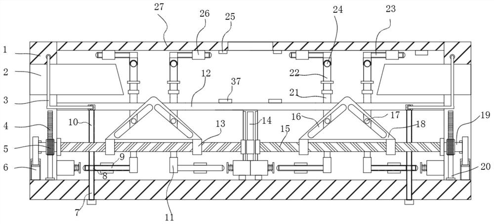
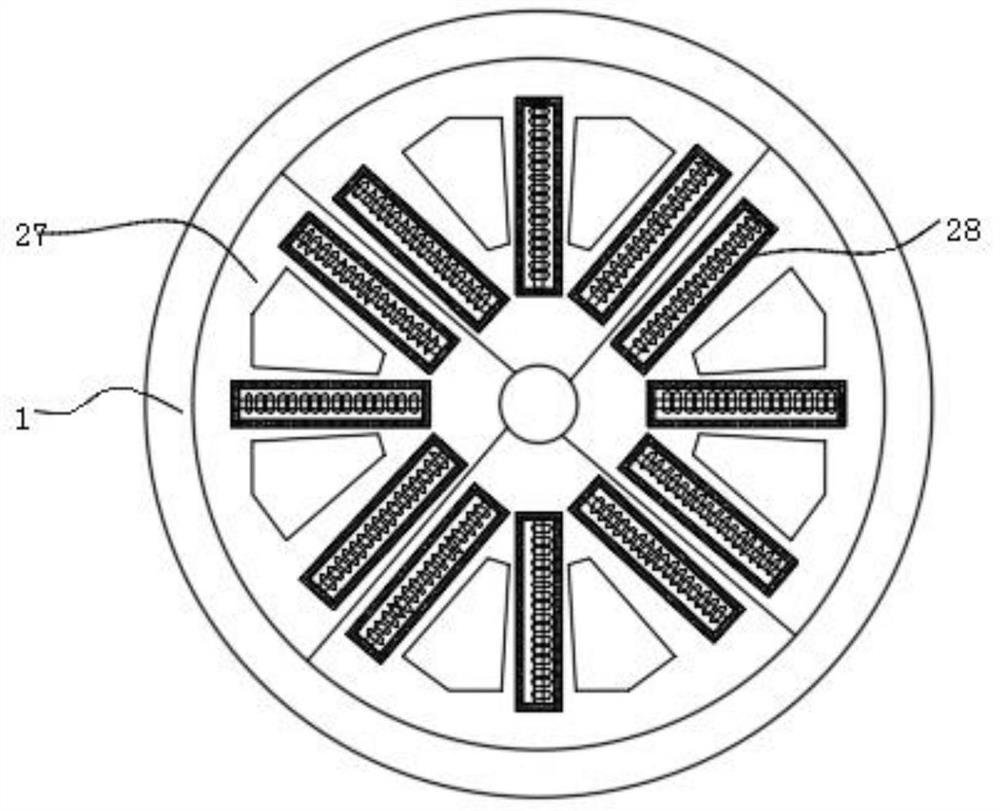
[0025] see Figure 1 to Figure 4 , the present invention provides a technical solution: a cutterhead of a shield machine for conveniently adjusting the cutter distance, comprising a body 1 and four mounting plates 27, the four mounting plates 27 are arranged in a circular array on the top of the body 1, and each mounting plate 27 The top is fixed with a plurality of cutter bodies 28, and each mounting plate 27 below is provided with a plug-in mechanism for ins...


PUM


Abstract

The invention discloses a shield tunneling machine cutter head convenient to adjust a cutter distance. The shield tunneling machine cutterhead convenient to adjust the cutter distance comprises a body and four mounting plates, the four mounting plates are annularly arrayed at the top of the body, a plurality of cutter bodies are fixed to the top of each mounting plate, an inserting mechanism used for mounting the mounting plates is arranged below each mounting plate, each inserting mechanism is connected with an angle deflection mechanism used for adjusting the angle of the mounting plate, the deflection mechanism is further connected with a compensation mechanism used for further adjusting the angle of the mounting plate, an angle monitoring assembly used for monitoring the angle of the mounting plate in real time is further arranged in the body, a mud water bin is formed in the portion, below the mounting plate, in the body, and a freezing mechanism used for freezing mud is arranged between the mud water bin and the mounting plate. According to the shield tunneling machine cutter head, the single mounting plate is detached, so that a single cutter can be conveniently replaced and maintained, and the working efficiency can be further improved.

Description

technical field [0001] The invention relates to the technical field of a shield machine cutter head, in particular to a shield machine cutter head for conveniently adjusting the cutter distance. Background technique [0002] In our country, it is customary to call the tunnel boring machine used in soft soil strata a shield machine, and the tunnel boring machine used in a rock stratum as a full-section tunnel boring machine. The basic working principle of shield tunneling method construction is a cylindrical steel component The soil is excavated while pushing forward along the axis of the tunnel. The shell of the cylindrical assembly is the shield, which acts as a temporary support for the excavated unlined tunnel section and bears the pressure of the surrounding soil layer, sometimes It also bears the groundwater pressure and keeps the groundwater out, and operations such as excavation, soil dumping, and lining are carried out under the cover of the shield. The existing shie...

Claims


Application Information

Patent Timeline
IPC IPC(8): E21D9/087E21D9/00E21F17/18
CPCE21D9/087E21D9/0873E21D9/001E21F17/18
Inventor 张宇何政徐功宇
Owner 张宇
Why Eureka
Try Eureka