

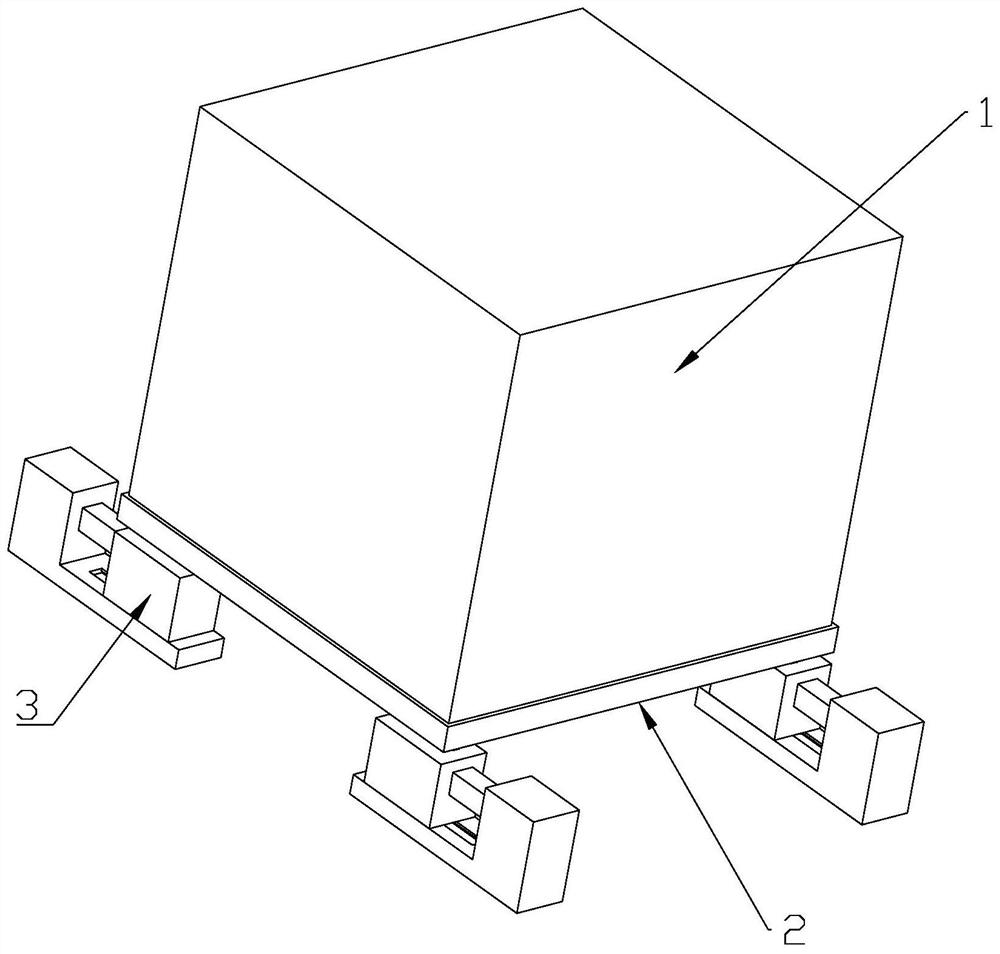
Supporting device for transformer of new energy automobile
A new energy vehicle and support device technology, applied in the direction of transformer/reactor installation/support/suspension, spring/shock absorber, vibration suppression adjustment, etc. To avoid problems such as poor performance, to avoid the decline of the shock absorption effect, increase the practicability, and increase the applicability
- Summary
- Abstract
- Description
- Claims
- Application Information
AI Technical Summary
Problems solved by technology
Method used
Image

Examples
specific Embodiment approach
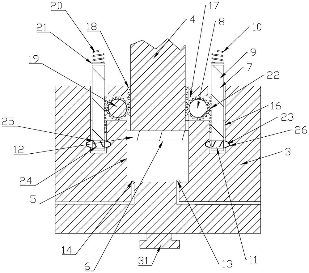
[0027] As an improved specific embodiment, the side of the first receiving hole 5 adjacent to the collision plate 15 is provided with a connecting channel 17 connected to the counterbore 16, the connecting piece 8 is arranged in the connecting channel 17, and the reducing The side of the shock rod 4 close to the connecting channel 17 is provided with a first tooth row 18, the connecting piece 8 includes a gear 19, the gear 19 meshes with the first tooth row 18, and the side of the rebound rod 9 close to the gear 19 is provided There is a second row of teeth 22 which meshes with the gear wheel 19 .
[0028] Through the above technical solution, through the linkage between the first gear row 18 , the gear 19 and the second gear row 22 , the maximum transmission efficiency can be obtained, and the stability and accuracy of rebounding can be guaranteed.
Embodiment approach
[0029] As an improved specific embodiment, the first elastic device 10 includes a first spring 20 and a pressure plate 21, and a second accommodation hole is provided on the support frame 2 corresponding to the position of the rebound rod 9, and the first spring One end of 20 is connected to the bottom of the second receiving hole, and the other end is connected to the pressing plate 21 , and the first spring 20 is used to keep the pressing plate 21 in contact with the resilient rod 9 .
[0030] Through the above-mentioned technical scheme, when receiving the longitudinal impact force, the rebound rod 9 moves to drive the pressure plate 21 to move toward the first spring 20, so that the first spring 20 obtains a rebound force. When rebounding, the first spring 20 drives The movement of the pressing plate 21 further drives the rebounding rod 9 to move for rebounding, and the quick rebounding can be realized through the arrangement of the first spring 20 and the pressing plate 21...
PUM
 Abstract
Description
Claims
Application Information