
Automatic correction method for low-voltage shunt monitoring equipment

A monitoring equipment and automatic calibration technology, applied in the low-voltage electrical field, can solve the problems of low deployment rate of inspection personnel, occupation, multi-manpower and time costs, and save manpower and time costs, save labor costs, and improve maintenance efficiency. Effect

Pending Publication Date: 2021-10-26
HANGZHOU THINGCOM INFORMATION TECH
View PDF0 Cites 0 Cited by
  • Summary
  • Abstract
  • Description
  • Claims
  • Application Information

AI Technical Summary

Problems solved by technology

[0003] The urban distribution network is becoming more and more complex, with more and more power distribution outlets, which brings a series of control problems in the operation and maintenance management stage, and the network scale continues to grow, but the number of personnel will remain relatively stable for a long time. Under the model, the problem of the company’s low deployment rate of inspection personnel is prominent. Provincial and municipal maintenance companies have many management equipment and a wide range of equipment. In some areas, the deployment rate of maintenance professionals is less than 50%. This conflicts with the rapidly growing grid scale. It is becoming more and more prominent, and there is an urgent need for a monitoring device that can locate and troubleshoot the faults of each branch line
[0004] Due to the existence of different batches in the prior art, there is a certain error in the parameters (such as resistance, capacitance, capacitance, etc.) There are certain deviations in current, power, temperature and other data, and the operation accuracy of the low-voltage shunt monitoring equipment itself is difficult to meet the needs of high-end customers
[0005] Therefore, the equipment needs to be calibrated before leaving the factory. In addition, at present, most of the workers manually perform a single calibration operation on the factory equipment, which requires too much manpower and time.

Method used


Image

  • Automatic correction method for low-voltage shunt monitoring equipment
  • Automatic correction method for low-voltage shunt monitoring equipment
  • Automatic correction method for low-voltage shunt monitoring equipment

Examples


Embodiment Construction

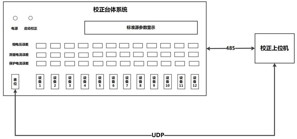
[0032] Attached below Figure 1-5 The present invention is described in detail. The implementation of the present invention needs to cooperate with the correction host computer software provided by the outside world and the calibration platform system that provides the standard source. The present invention implements the low-voltage shunt monitoring equipment, calibration host computer software, and calibration based on the network communication protocol. Information exchange between platform and body systems, such as figure 1 shown.

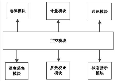
[0033] Such as figure 2 As shown, the control circuit includes a main control module, a power module, a metering module, a communication module, a temperature acquisition module and a status indication module; the metering module is connected to the main control module through an SPI interface, and the metering module has a built-in metering chip. The main control module is then connected to the communication module, temperature acquisition ...


PUM


Abstract

The invention discloses an automatic correction method for low-voltage shunt monitoring equipment. According to the invention, information interaction among the low-voltage shunt monitoring equipment, the correction upper computer software and the correction table body system is realized based on a network communication protocol, and when an error exists between an electrical parameter acquired by the low-voltage shunt monitoring equipment and a standard value provided by the correction table body system, different electrical parameters of a plurality of low-voltage shunt monitoring equipment can be corrected at the same time through the correction upper computer software, and a correction compensation coefficient is calculated according to the deviation between an actual measurement value and a theoretical value so that the purpose of correction is achieved, and the measurement precision of the low-voltage shunt monitoring equipment is improved. According to the invention, the requirements of informatization monitoring and on-site indication are both considered.

Description

technical field [0001] The invention belongs to the field of low-voltage electrical technology, and in particular relates to an automatic correction method for low-voltage shunt monitoring equipment. Background technique [0002] In recent years, my country's distribution network construction investment has continued to increase, the development of distribution network has achieved remarkable results, and the distribution network has become more and more complex; however, the complexity of the distribution network also makes it difficult to monitor its faults. Nowadays, power accidents are mainly concentrated in the redistribution network. According to statistics, 400V low-voltage distribution network failures account for 90%. [0003] The urban distribution network is becoming more and more complex, with more and more power distribution outlets, which brings a series of control problems in the operation and maintenance management stage, and the network scale continues to gr...

Claims


Application Information

Patent Timeline
IPC IPC(8): G01R35/00
CPCG01R35/005
Inventor 胡晓双陈科明吴耀增曾佳
Owner HANGZHOU THINGCOM INFORMATION TECH
Features
  • Generate Ideas
  • Intellectual Property
  • Life Sciences
  • Materials
  • Tech Scout
  • Unparalleled Data Quality
  • Higher Quality Content
  • 60% Fewer Hallucinations
Learn More