Pyrolytic particle fire detection method and detector

A fire detector and fire detection technology, applied in the direction of electrical fire alarms, etc., can solve the problems of low early warning accuracy, inability to achieve very early detection and early warning of electrical fires, etc., and achieve the effect of improving early warning accuracy.

Pending Publication Date: 2021-10-26
WUXI SHENGMIN SENSING TECH
View PDF6 Cites 2 Cited by
  • Summary
  • Abstract
  • Description
  • Claims
  • Application Information

AI Technical Summary

Problems solved by technology

[0003] The purpose of the present invention is to provide a pyrolysis particle fire detection method and a detector to alleviate the problems in the prior art that only the concentration of pyrolysis particles is used as the influencing factor for early warning, the early warning accuracy rate is low, and the electrical fire cannot be realized. Technical issues of very early detection and early warning

Method used


Image

  • Pyrolytic particle fire detection method and detector
  • Pyrolytic particle fire detection method and detector
  • Pyrolytic particle fire detection method and detector

Examples


Embodiment 1

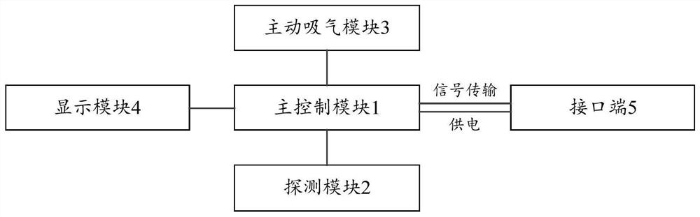
[0032] figure 1It is a schematic structural diagram of a pyrolytic particle fire detector provided by an embodiment of the present invention. like figure 1 As shown, the pyrolysis particle fire detector may include the following modules: a main control module 1 and a detection module 2 including a plurality of sensing devices. The connection relationship between the two is: the detection module 2 is connected to the main control module 1 , that is, each sensor is connected to the main control module 1 . The function of the main control module 1 is analyzed as follows:

[0033] The main control module 1 is used to obtain multiple parameter data of the pyrolysis particles and / or the environment where the pyrolysis particles are located in the closed space of the pyrolysis particle fire detector through multiple sensor devices; and then judge whether each parameter data exceeds The corresponding preset threshold; if each parameter data does not exceed the corresponding preset ...

Embodiment 2

[0054] According to an embodiment of the present invention, an embodiment of a pyrolysis particle fire detection method is provided, and the method is applied to the pyrolysis particle fire detector in the above-mentioned embodiment 1. It should be noted that the steps shown in the flowcharts of the accompanying drawings may be implemented in a computer system, such as a set of computer-executable instructions, and that although a logical order is shown in the flowcharts, in some cases, The steps shown or described may be performed in an order different than here.

[0055] Image 6 It is a flowchart of a pyrolysis particle fire detection method provided by an embodiment of the present invention. like Image 6 As shown, the method includes the following steps S101 to S104:

[0056] Step S101, obtaining multiple parameter data of the pyrolysis particles and / or the environment in which the pyrolysis particles are located in the enclosed space of the pyrolysis particle fire det...


PUM


Abstract

The invention provides a pyrolytic particle fire detection method and detector, and relates to the technical field of fire detection, and the method comprises the steps: firstly obtaining a plurality of parameter data of pyrolytic particles and/or an environment where the pyrolytic particles are located in a closed space of the pyrolytic particle fire detector; then judging whether each parameter datum exceeds a corresponding preset threshold value or not; if each piece of parameter data does not exceed the corresponding preset threshold value, performing fusion processing on all the parameter data by using a weight algorithm fusion technology to obtain parameter fusion data; and finally, based on the parameter fusion data and a preset pyrolysis particle alarm threshold, obtaining a pyrolysis particle fire detection result. According to the invention, a real and effective pyrolytic particle fire detection result can be obtained by fusing various parameter data by adopting a weight algorithm fusion technology, the early warning accuracy is improved, and extremely early detection and early warning of the fire can be realized.

Description

technical field [0001] The invention relates to the technical field of fire detection, in particular to a pyrolysis particle fire detection method and a detector. Background technique [0002] The heat generated in the early stages of an electrical fire can cause the thermal decomposition of the outer insulation layer of the wire, which in turn produces pyrolytic particles. The existing electrical fire protection technology uses pyrolytic particle detectors to monitor changes in the concentration of pyrolytic particles in the protected area for early detection and early warning of fires. However, this detection method only takes the concentration of pyrolysis particles as the influencing factor for early warning, and the accuracy of early warning is low, so it is impossible to achieve very early detection and early warning of electrical fires. Contents of the invention [0003] The purpose of the present invention is to provide a pyrolysis particle fire detection method a...

Claims


Application Information

Patent Timeline
Patent Type & Authority Applications(China)
IPC IPC(8): G08B17/06
CPCG08B17/06
Inventor 宋珍刘星蔡奕康
Owner WUXI SHENGMIN SENSING TECH
Why Eureka
Try Eureka