
Adjustable power transmission cable installation device

A technology for power transmission and installation equipment, which is applied in the direction of cable installation, cable installation devices, and cable laying equipment. It can solve problems such as lifting the installation position of cables and difficult penetration of cables, and achieves the effect of preventing damage

Pending Publication Date: 2021-10-26
安徽永汇新材料科技有限公司
View PDF0 Cites 2 Cited by
  • Summary
  • Abstract
  • Description
  • Claims
  • Application Information

AI Technical Summary

Problems solved by technology

[0003] During the installation process, the cables often pass through some walls, which makes it difficult to lift the cables to an accurate installation position, and it is difficult for the cables to penetrate into the cable protection tube when installed at a high place. Therefore, the present invention proposes An adjustable power transmission cable installation device capable of solving the above problems

Method used


Image

  • Adjustable power transmission cable installation device
  • Adjustable power transmission cable installation device
  • Adjustable power transmission cable installation device

Examples


Embodiment 1

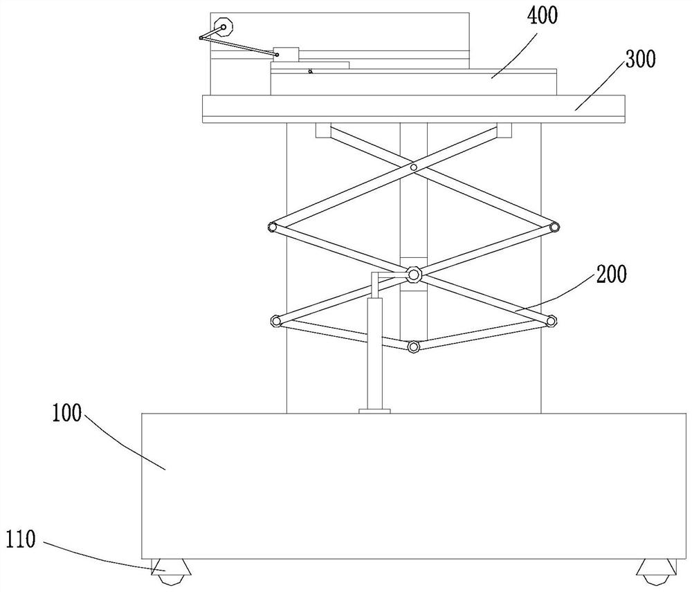
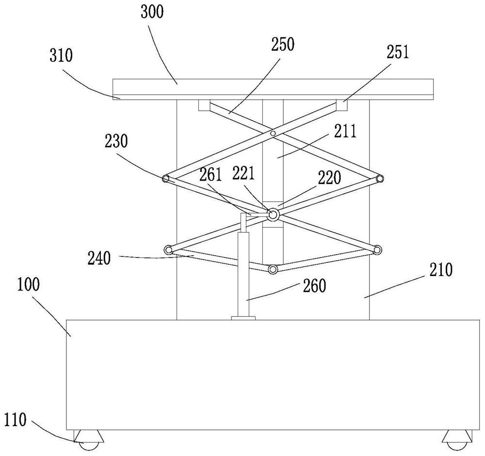
[0033] The present invention provides a technical solution: an adjustable power transmission cable installation device, including a support base 100, a moving wheel set 110 is installed on the bottom of the support base 100, and the moving wheel set 110 is a universal wheel;

[0034] Movable plate 300, the movable plate 300 is arranged above the support seat 100, the movable plate 300 is provided with a clamping mechanism 400 for placing and clamping cables, the clamping mechanism 400 includes a fixed plate 410 arranged on the upper end of the movable plate 300, fixed The upper end of the plate 410 is provided with an arc-shaped groove 411, one end of the arc-shaped groove 411 is the threading port, and the other end is the cable outlet. A cover plate 420 is provided on the side, and a pressing block 421 is provided on the lower side of the cover plate 420, and the pressing block 421 is pressed against the upper and outer surfaces of the cable;

[0035] Lifting mechanism 200. ...

Embodiment 2

[0038] On the basis of Embodiment 1, the lifting mechanism 200 includes a vertical plate 210 arranged on the upper end of the support base 100. The vertical plate 210 is provided with a chute 211, and a moving block 220 is slidingly connected in the chute 211. The outer wall of the moving block 220 is provided with Connecting column 221, two groups of elevating rods 230 are intersected on connecting column 221, the middle parts of two groups of elevating rods 230 are hinged, and the lower ends of two groups of elevating rods 230 are respectively hinged with bottom elevating rods 240, and bottom elevating rods 240 extend downwards and Hinged with the bottom of the chute 211, the tops of the two sets of lifting rods 230 are respectively hinged with top lifting rods 250, the two sets of top lifting rods 250 are arranged crosswise and hinged, the tops of the lifting rods are respectively provided with sliders 251, and the lower side of the movable plate 300 A moving slot is provide...

Embodiment 3

[0043] On the basis of Embodiment 1 or Embodiment 2, the bottom wall of the arc-shaped groove 411 is set obliquely downward from the threading opening to the outlet, and several groups of balls 413 are arranged on the bottom wall of the arc-shaped groove 411, and the arc-shaped groove 411 is wired A guide ring 412 is provided at the mouth, and the cable passes through the outlet along the guide ring 412, so that the lower outer surface of the cable is always in rolling contact with several groups of balls 413 along the bottom wall of the arc groove 411 of the ball 413;

[0044] The movable plate 300 is provided with a shelf plate 430 on one side of the fixed plate 410, and the shelf plate 430 is provided with a transverse groove 431, and a reciprocating block 432 is slidingly connected in the transverse groove 431, and the reciprocating block 432 is connected with the cover plate 420, and the shelf plate 430 is also installed There is a driving motor 440, the output shaft of th...


PUM


Abstract

The invention discloses an adjustable power transmission cable mounting device, and the device comprises a supporting seat, wherein a moving wheel set is mounted at the bottom of the supporting seat, and the moving wheel set is a universal wheel; a movable plate which is arranged above the supporting seat, wherein the movable plate is provided with a clamping mechanism used for placing and clamping a cable, the clamping mechanism comprises a fixed plate arranged at the upper end of the movable plate, the upper end of the fixed plate is provided with an arc-shaped groove, one end of the arc-shaped groove is a threading opening, the other end of the arc-shaped groove is a cable outlet, the cable enters the arc-shaped groove from the threading opening and penetrates out of the cable outlet, the arc-shaped groove is provided with a cover plate on the upper side of the threading port, and the lower side of the cover plate is provided with an abutting block which abuts against the upper outer side face of the cable; and a lifting mechanism which is arranged in the middle of the upper end of the supporting seat and used for driving the movable plate to rise. The outer side face of the cable is tightly abutted, so that the cable is clamped on the movable plate to be kept stable, the lifting mechanism drives the movable plate to rise, and the cable is conveyed to the specific height position where the cable needs to be installed.

Description

technical field [0001] The invention relates to the technical field of power transmission, in particular to an adjustable power transmission cable installation device. Background technique [0002] Due to the gradual increase in electricity demand, the cables used for power transmission also gradually increase, and the cables need to be installed during the power transmission process. [0003] During the installation process, the cables often pass through some walls, which makes it difficult to lift the cables to an accurate installation position, and it is difficult for the cables to penetrate into the cable protection tube when installed at a high place. Therefore, the present invention proposes An adjustable power transmission cable installation device capable of solving the above problems. Contents of the invention [0004] The purpose of the present invention is to provide an adjustable power transmission cable installation device to solve the problems raised in the ...

Claims


Application Information

Patent Timeline
Patent Type & Authority Applications(China)
IPC IPC(8): H02G1/04H02G1/08B66F7/06B66F7/08
CPCH02G1/04H02G1/088B66F7/0666B66F7/08
Inventor 许来沈六六时霞锋王孝晴郭鹏生夏林褚娜娜
Owner 安徽永汇新材料科技有限公司
Learn More