Eureka AIR delivers breakthrough ideas for toughest innovation challenges, trusted by R&D personnel around the world.

Special-shaped injection molding part production mold with rapid mold opening function

A technology for injection molded parts and special-shaped parts, which is applied in the field of molds for the production of special-shaped injection molded parts. It can solve the problems of lower production quality of workpieces, easy misalignment of the joint between the upper mold and the lower mold, and unstable use, so as to enhance the effect of pressing down and enhance Connection strength, the effect of enhancing connectivity

Active Publication Date: 2021-10-29
欧斯普模具科技南通有限公司
View PDF3 Cites 2 Cited by
  • Summary
  • Abstract
  • Description
  • Claims
  • Application Information

AI Technical Summary

Problems solved by technology

[0003] Existing molds for the production of special-shaped injection molded parts with rapid mold opening function usually use hydraulic pumps and hydraulic lifting rods to control the upper mold, so as to realize rapid mold opening and closing between the upper mold and the lower mold, but because the hydraulic lifting rod It is movably connected with the upper mold. After the upper mold and the lower mold are closed, when the mold is injected into the mold, the upper mold will be instantly lifted by a large amount of hot air, which will cause the joint between the upper mold and the lower mold to be easily misaligned, and the use is unstable. , resulting in a reduction in the production quality of the workpiece in the mold

Method used


Image

  • Special-shaped injection molding part production mold with rapid mold opening function
  • Special-shaped injection molding part production mold with rapid mold opening function
  • Special-shaped injection molding part production mold with rapid mold opening function

Examples


Embodiment

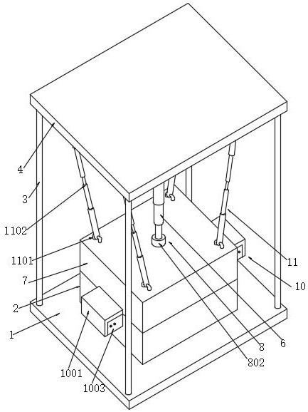
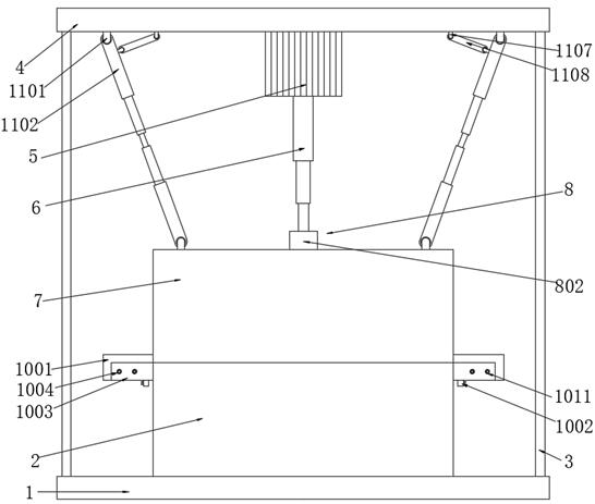
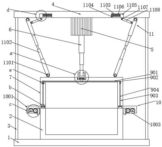
[0033] Example: such as Figure 1-8 As shown, the present invention provides the following technical solutions: a mold for the production of special-shaped injection molded parts with a rapid mold opening function, which includes a base plate 1, a lower mold 2, a column 3, and a top plate. 4. Hydraulic pump 5, hydraulic lifting rod 6, upper mold 7, transmission component 8, fixed component 9;

[0034] A lower mold 2 is fixedly installed in the middle position of the upper end of the base plate 1, and a column 3 is fixedly installed around the upper end of the base plate 1, and a top plate 4 is fixedly installed on the top of the column 3, and a hydraulic pressure is fixedly installed in the middle position of the lower end of the top plate 4. pump 5, the output end of the hydraulic pump 5 is fixedly connected with a hydraulic lifting rod 6, the telescopic end of the hydraulic lifting rod 6 is fixedly connected with an upper die 7, and the upper die 7 is provided with a transmi...


PUM


Abstract

The invention discloses a special-shaped injection molding part production mold with a rapid mold opening function. The special-shaped injection molding part production mold with the rapid mold opening function comprises an upper mold, a transmission assembly and a fixing assembly, wherein the transmission assembly is arranged on the upper mold; and the fixing assembly is fixedly connected onto the transmission assembly. When a hydraulic lifting rod controls the upper mold to move downwards, a sliding plate is controlled by the telescopic end of the hydraulic lifting rod to continue to move downwards to press a moving plate, so that an abutting rod gradually extends downwards in a penetrating hole, and the abutting rod is conveniently controlled to extrude a first transmission rod; a second transmission rod can be extruded through transverse movement of the first transmission rod, so that the second transmission rod moves downwards in a longitudinal moving cavity; the second transmission rod penetrates through an open hole in the downward moving process and extrudes a moving block in a moving cavity, so that the moving block can compress a first reset spring in the moving cavity to transversely move, then a fixing rod is driven to be inserted into a fixing hole through an inserting hole, the connectivity of the upper mold and the lower mold can be enhanced, and upper hot air jacking in the injection molding process of the upper mold is avoided.

Description

technical field [0001] The invention relates to the technical field of injection molds, in particular to a mold for producing special-shaped injection molded parts with the function of rapid mold opening. Background technique [0002] Injection molds are divided into thermosetting plastic molds, automobile molds, and thermoplastic plastic molds according to their molding characteristics; Injection molds, etc., in which hot pressing molds can be divided into three types: overflow type, semi-overflow type, and non-overflow type according to the overflow method, and injection molds can be divided into two types: cold runner mold and hot runner mold according to the gating system; The installation and disassembly methods can be divided into two types: mobile type and fixed type. [0003] Existing molds for the production of special-shaped injection molded parts with rapid mold opening function usually use hydraulic pumps and hydraulic lifting rods to control the upper mold, so ...

Claims


Application Information

Patent Timeline
Patent Type & Authority Applications(China)
IPC IPC(8): B29C45/26B29C45/67B29C45/64
CPCB29C45/2602B29C45/2606B29C45/67B29C45/641
Inventor 张杰王睿杰邢东
Owner 欧斯普模具科技南通有限公司
Why Eureka
Eureka Blog
Learn More