Indoor decorative stone laying equipment and process

A technology for interior decoration and stone materials, which is applied in the direction of architecture and building construction. It can solve the problems of machine jamming, inability to pick up mortar at fixed points, and easy accumulation of additives, etc., and achieve the effect of consistent mortar volume.

Active Publication Date: 2021-10-29
百合盛华建筑科技有限公司
View PDF8 Cites 0 Cited by
  • Summary
  • Abstract
  • Description
  • Claims
  • Application Information

AI Technical Summary

Problems solved by technology

[0008] Aiming at the above-mentioned deficiencies in the prior art, the present invention provides an indoor decorative stone laying equipment, which is used to solve the existing tile paving construction equipment. After the operator cuts the tiles, he needs to occupy the ground s...

Method used


Image

  • Indoor decorative stone laying equipment and process
  • Indoor decorative stone laying equipment and process
  • Indoor decorative stone laying equipment and process

Examples


Embodiment 1

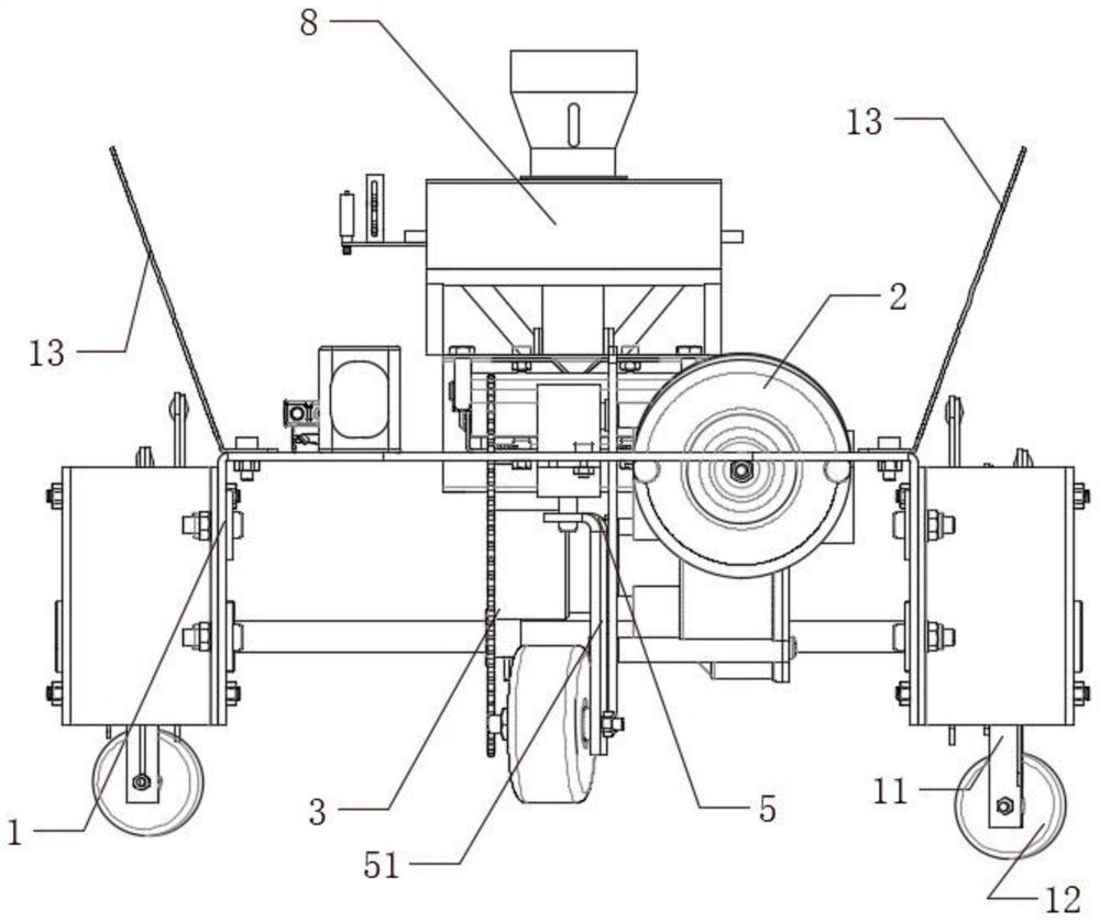
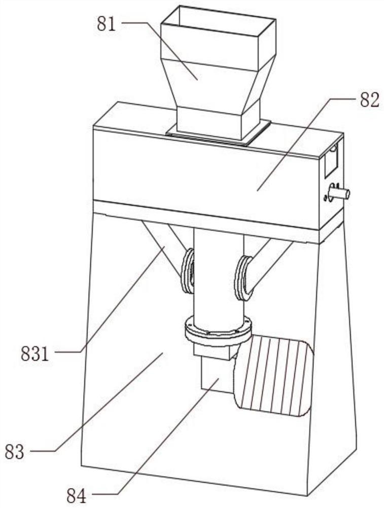
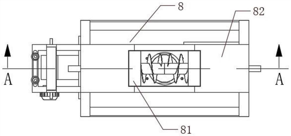
[0051] An indoor decorative stone laying equipment, comprising a driving mechanism 1, a power mechanism 2 and a cutting mechanism 3, the power mechanism 2 and the cutting mechanism 3 are arranged at the lower end of the driving mechanism 1 and connected with the driving mechanism 1, and the upper end of the driving mechanism 1 is also provided with The brick body sizing device 8, the brick body sizing device 8 is a guide cover body 81, a material adding part 82, and a mixing part 83 from top to bottom. The first material unit 821 and the second material pushing unit 822 rotate to stir the material and push it to both sides. The outside of the mixing part 83 is provided with a connecting cylinder 831 and a valve body 832 for controlling the flow of the material. The mixing part 83 passes through the connecting cylinder 831. It communicates with the feeding part 82, and the mixing part 83 is provided with a mixing unit 833. When the mixing unit 833 stirs and pushes the material u...

Embodiment 2

[0064] Embodiment As a further improvement of the previous embodiment, as Figure 1-7 As shown, a kind of indoor decorative stone laying equipment of the present invention comprises a driving mechanism 1, a power mechanism 2 and a cutting mechanism 3, the power mechanism 2 and the cutting mechanism 3 are arranged at the lower end of the driving mechanism 1 and connected with the driving mechanism 1, and the driving mechanism The upper end of 1 is also provided with a brick body sizing device 8, and the brick body sizing device 8 is a guide cover body 81, a material adding part 82, and a mixing part 83 from top to bottom. The second material unit 822, the first material pushing unit 821 and the second material pushing unit 822 rotate to stir the material and push it to both sides. The outside of the mixing part 83 is provided with a connecting cylinder 831 and a valve body 832 for controlling the flow of the material. The mixing part 83 communicates with the feeding part 82 thr...


PUM


Abstract

The invention belongs to the technical field of mechanical equipment, and particularly relates to indoor decorative stone laying equipment. The indoor decorative stone laying equipment comprises a traveling mechanism, a power mechanism and a cutting mechanism, wherein the power mechanism and the cutting mechanism are arranged on the lower end of the traveling mechanism and are connected with the traveling mechanism, a brick body sizing device is further arranged on the upper end of the traveling mechanism, the brick body sizing device comprises a guiding cover body, a material adding part and a mixing part from top to bottom, a first material pushing unit and a second material pushing unit are arranged in the material adding part, and the first material pushing unit and the second material pushing unit rotate to stir materials and push the materials towards the two sides. According to the indoor decorative stone laying equipment, the problems that after a ceramic tile is cut by an operator, mortar needs to be proportioned independently on the ground, the operator must run back and forth, the mortar cannot be taken and smeared on the back face of the ceramic tile at a fixed point, additionally, when too much materials are added, added materials are easy to accumulate or cake, and a machine is stuck in existing ceramic tile paving construction equipment are solved.

Description

technical field [0001] The invention belongs to the technical field of mechanical equipment, and in particular relates to an interior decorative stone laying equipment and process. Background technique [0002] Laying floor tiles on the ground is a decoration method commonly used in many families and public places today. Floor tiles are a kind of floor decoration materials, also called floor tiles. It has a variety of specifications, strong quality, pressure resistance, wear resistance, and moisture resistance. Some are glazed for decoration. It is mostly used for the ground and floor of public buildings and civil buildings. [0003] The existing floor tile laying process generally includes wet laying method and dry laying method. Among them, the wet laying method is the floor tile laying method commonly used by many home improvement owners. The tile floor using the wet laying method may produce empty drums and air bubbles. It affects the service life of the floor tiles,...

Claims


Application Information

Patent Timeline
IPC IPC(8): E04F21/22E04F21/02
CPCE04F21/22E04F21/023
Inventor 张良武应建方李立伟赵兴钱邹小建楼焜胡易晗李昌民
Owner 百合盛华建筑科技有限公司
Why Eureka
Try Eureka