Efficient portable flood control emergency pump
A portable emergency pump technology, applied in the field of life, can solve the problems of low efficiency and poor portability of emergency pumps, and achieve the effects of saving labor input, avoiding manual push, and reducing labor burden
- Summary
- Abstract
- Description
- Claims
- Application Information
AI Technical Summary
Problems solved by technology
Method used
Image
Examples
Embodiment 1
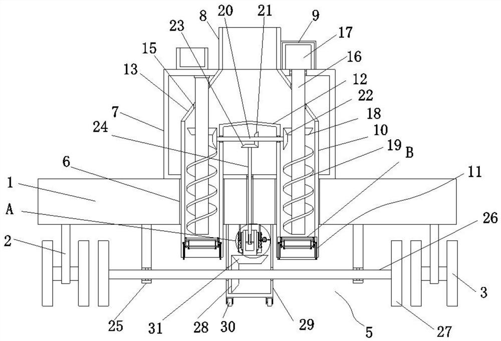
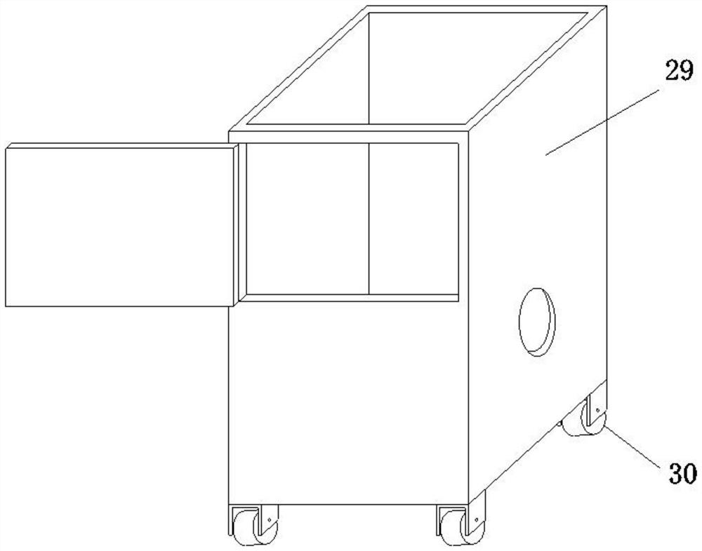
[0030] Embodiment one, by Figure 1 to Figure 5 Given, the present invention includes a support plate 1 and a pump body 7, the pump body 7 is installed on the top of the support plate 1, the bottom end of the support plate 1 is symmetrically provided with a support seat 2, and both sides of the bottom end of the support seat 2 are provided with movable Wheel 3, the middle position of the bottom end of support plate 1 is provided with drive wheel set 5, through the design of moving wheel 3 and drive wheel set 5, it is convenient to realize the movement of the device, improves the portability of the device, and can provide power for the movement of the device at the same time, To avoid manual pushing, thereby reducing the labor burden, the support plate 1 is symmetrically provided with a through groove 16, and the inside of the through groove 16 is interspersed with a suction pipe 10 extending to the inside of the pump body 7, through which the two suction pipes 10 The design ef...
Embodiment 2
[0032] Embodiment two, on the basis of embodiment one, by figure 1 Given, the top of the sealing box 12 is provided with a conical cover, and the top of the pump body 7 is provided with a storage box. Through the design of the conical cover, the drawn water can be diverted to prevent water from accumulating on the top of the sealing box 12. , through the design of the storage box, it is convenient to store the maintenance tools, thereby improving the storage performance of the device.
Embodiment 3
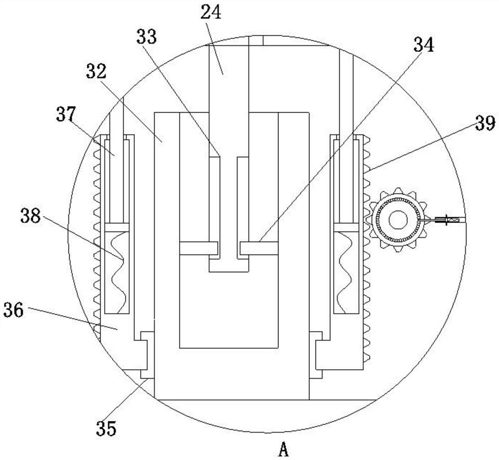
[0033] Embodiment three, on the basis of embodiment one, by figure 1 , image 3 and Figure 4 Given, the linkage includes bevel gear four 23, linkage shaft 24, bevel gear six 31, sleeve 32, chute 33, slide bar 34, snap ring 35, adjustment cylinder 36, gear teeth 39 and adjustment parts, linkage The shaft 24 is installed inside the sealing box 12, and the bottom end of the linkage shaft 24 extends to the bottom of the support plate 1, and the top of the linkage shaft 24 is provided with a bevel gear 4 23 meshed with the bevel gear 2 21, and the linkage shaft 24 The bottom end of the sleeve 32 is provided with a sleeve 32, and the two sides of the sleeve 32 are symmetrically provided with a slide bar 34, and the bottom sides of the linkage shaft 24 are provided with a chute 33 slidingly connected with the slide bar 34, and the bottom end of the sleeve 32 is provided with There is a bevel gear 31, the outer wall of the sleeve 32 is connected with a snap ring 35, the outer wall ...
PUM
 Abstract
Description
Claims
Application Information
 - R&D
- Intellectual Property
- Life Sciences
- Materials
- Tech Scout
- Unparalleled Data Quality
- Higher Quality Content
- 60% Fewer Hallucinations
Browse by: Latest US Patents, China's latest patents, Technical Efficacy Thesaurus, Application Domain, Technology Topic, Popular Technical Reports.
© 2025 PatSnap. All rights reserved.Legal|Privacy policy|Modern Slavery Act Transparency Statement|Sitemap|About US| Contact US: help@patsnap.com


