Combined hydraulic retarder

A hydraulic retarder, combined technology, applied in the direction of hydraulic resistance brakes, brake types, mechanical equipment, etc., can solve the problems of increasing the difficulty of manufacturing and installation, and achieve the effects of simple disassembly, easy manufacturing and simple structure.

Pending Publication Date: 2021-10-29
贵州凯星液力传动机械有限公司
View PDF13 Cites 0 Cited by
  • Summary
  • Abstract
  • Description
  • Claims
  • Application Information

AI Technical Summary

Problems solved by technology

Since many transmissions are not equipped with a hydraulic retarder, adding a hydraulic retarder at the end of the transmission requires changing the transmission structure, which increases the difficulty of manufacturing and installation

Method used


Image

  • Combined hydraulic retarder
  • Combined hydraulic retarder
  • Combined hydraulic retarder

Examples


Embodiment 1

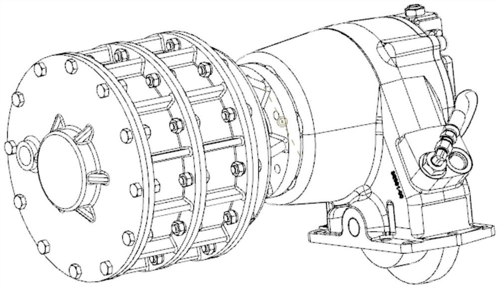
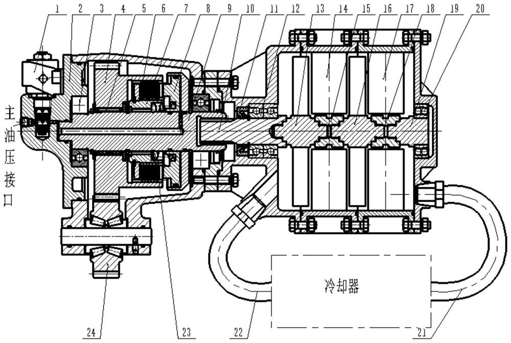
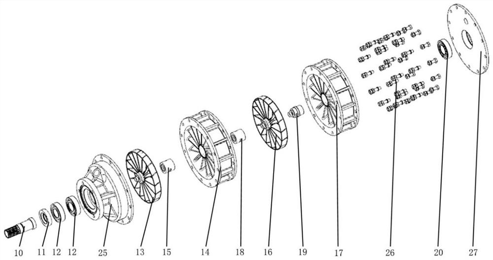
[0020] Such as Figure 1 to Figure 3 A combined hydraulic retarder shown includes a power take-off input gear 24; the power take-off input gear 24 meshes with a transmission power take-off gear hub 4, and a spline gear hub 7 is installed on the power take-off gear hub 4, The end of the spline gear hub 7 close to the power take-off gear hub 4 is equipped with a clutch friction plate 6, the spline gear hub 7 is fixed on the piston 8, and the movement of the piston 8 is controlled by the main oil pressure interface pipeline; the spline gear hub 7 Coaxial meshing transmission retarder assembly, electric drive rotation structure composed of multiple sets of stators and rotors coaxially installed in the retarder assembly.

Embodiment 2

[0022] Based on Embodiment 1, and, the moving direction of the piston 8 and the rotational axis of the power take-off gear hub 4 are located on the same straight line.

Embodiment 3

[0024] Based on Embodiment 1, and the retarder assembly is connected with a cooler through a rubber oil outlet pipe 21 and a rubber oil inlet pipe 22 .


PUM


Abstract

The invention provides a combined hydraulic retarder. The combined hydraulic retarder comprises a power takeoff input gear. The power takeoff input gear is in engaged transmission with a power takeoff gear hub, a spline gear hub is installed on the power takeoff gear hub, a clutch friction plate is installed at the end, close to the power takeoff gear hub, of the spline gear hub, the spline gear hub is fixed to a piston, and the piston communicates through a main oil pressure connector pipeline and is controlled to move. The spline gear hub is coaxially engaged with a transmission retarding assembly, and the retarding assembly is internally and coaxially provided with an electric drive rotating structure composed of a plurality of sets of stators and rotors. According to the combined hydraulic retarder, the combined hydraulic retarder is mounted at a power takeoff port. The combined hydraulic retarder does not interfere with a transmission, can realize a retarding function for the transmission, and is very convenient to mount and dismount; and the combined hydraulic retarder is simple in structure, safe, reliable and easy to disassemble and assemble, the number of rotors and stators can be adjusted according to different vehicle types, the brake requirements of different vehicles can be better met, and manufacturing is easy.

Description

technical field [0001] The invention relates to a combined hydraulic retarder. Background technique [0002] The hydraulic retarder is mainly used on large and heavy vehicles. When the vehicle is on a long downhill section, it acts as a deceleration brake, so that the driver does not have to step on the brake for a long time, which reduces the wear of the brake, improves the safety of driving, and reduces the Driver's labor intensity. Since many transmissions are not equipped with a hydraulic retarder, adding a hydraulic retarder at the end of the transmission requires changing the transmission structure, which increases the difficulty of manufacture and installation. Contents of the invention [0003] In order to solve the above technical problems, the present invention provides a combined hydraulic retarder, which can realize the retarding function for the transmission, and is very convenient to install and disassemble. [0004] The present invention is achieved throug...

Claims


Application Information

Patent Timeline
IPC IPC(8): F16D57/00
CPCF16D57/00F16D57/005
Inventor 蒋辰希张承元李世鹏
Owner 贵州凯星液力传动机械有限公司
Why Eureka
Try Eureka