
Dehumidification device

A filter layer and shell technology, which is applied in the field of dehumidification devices, can solve problems such as low working efficiency, and achieve the effects of improving efficiency, improving dehumidification efficiency, and reducing the number of replacements

Active Publication Date: 2021-10-29
安第斯浙江能源科技有限公司
View PDF5 Cites 2 Cited by
  • Summary
  • Abstract
  • Description
  • Claims
  • Application Information

AI Technical Summary

Problems solved by technology

In southern my country or coastal areas, the air is relatively humid, especially during the rainy season. In order to ensure the dehumidification effect, the dehumidifier needs to replace the dehumidification filter frequently, resulting in low work efficiency.

Method used


Image

  • Dehumidification device
  • Dehumidification device
  • Dehumidification device

Examples


Embodiment 1

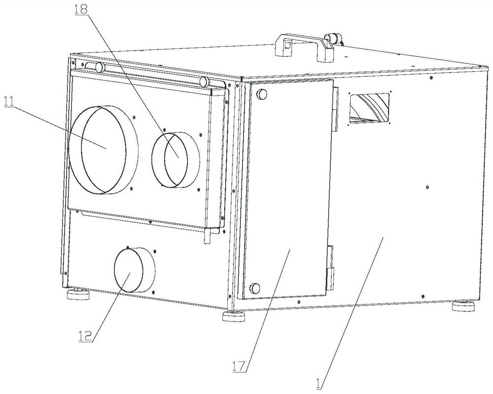
[0029] combined with figure 1 -

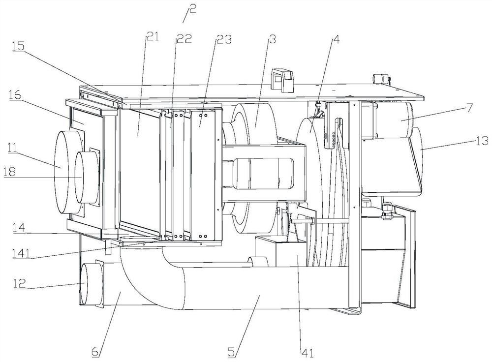
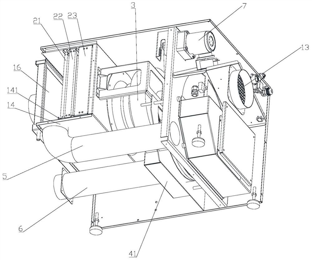
[0030] 3. The dehumidification device of this embodiment is characterized in that it includes a housing 1 and an air inlet 11, an air return port 12, and an air outlet 13 arranged on the housing 1, and the housing 1 is provided with a filter assembly 2, a fan 3. The runner 4, the clean air duct 5 and the return air duct 6, the filter assembly 2 is connected to the air inlet 11, one side of the fan 3 is connected to the filter assembly 2, and the other side of the fan 3 is connected to the runner 4, One end of the return air duct 6 is connected to the runner 4, the other end of the return air duct 6 is connected to the return air outlet 12, one end of the clean air duct 5 is connected to the side of the runner 4 away from the fan 3, and the other end of the clean air duct 5 is The air inlet 11 is used to enter moist air, the air outlet 13 is used to discharge dry air, and the air return port 12 is used to discharge moisture in the runner 4 . ...

Embodiment 2

[0032] combined with figure 1 -

[0033] 3. Compared with the technical solution of Example 1, the dehumidification device of this embodiment can be improved as follows: the filter assembly 2 includes a first filter layer 21, a second filter layer 22 and a third filter layer 23 arranged in sequence, The first filter layer 21 is connected to the air inlet 11 , the third filter layer 23 is connected to the fan 3 , and the thicknesses of the first filter layer 21 , the second filter layer 22 and the third filter layer 23 are sequentially increased. The moisture absorption ability of the first filter layer 21, the second filter layer 22 and the third filter layer 23 is sequentially enhanced, and the moisture and salt in the air are fully absorbed, and the dehumidification rate of the runner 4 is accelerated, which can significantly improve the air dehumidification. Salt efficiency.

Embodiment 3

[0035] combined with figure 1 -

[0036] 3. Compared with the technical solution of embodiment 1 or 2, the dehumidification device of this embodiment can be improved as follows: a first support plate 14 and a second support plate 15 are provided inside the housing 1, and the first support plate The plate 14 and the second support plate 15 are respectively provided with a draw-in groove 141, and the two ends of the first filter layer 21, the two ends of the second filter layer 22, and the two ends of the third filter layer 23 are all slidably fitted with the draw-in groove 141 . When the first filter layer 21, the second filter layer 22 or the third filter layer 23 needs to be replaced after a long period of use, the first filter layer 21, the second filter layer 22 or the third filter layer 23 can be directly removed from the card It can be pulled out from the slot 141, which is very convenient and saves the time of installation and disassembly.


PUM


Abstract

The invention discloses a dehumidification device, and relates to the technical field of dehumidification. The dehumidification device comprises a shell and an air inlet, an air return port and an air outlet which are formed in the shell, a filter assembly, a fan, a rotating wheel, an air purification pipeline and an air return pipeline are arranged in the shell, the filter assembly communicates with the air inlet, one side of the fan is connected with the filter assembly, and the other side of the fan is connected with the rotating wheel. One end of the air return pipeline is connected with the rotating wheel, the other end of the air return pipeline is connected with the air return port, one end of the air purification pipeline communicates with the face, away from the fan, of the rotating wheel, and the other end of the air purification pipeline communicates with the filter assembly. The air inlet is used for entering humid air, the air outlet is used for discharging dry air, and the air return port is used for discharging moisture in the rotating wheel. The air purification pipeline and the air return pipeline enable the filter assembly and the rotating wheel to have the capacity of continuously absorbing the moisture correspondingly, the service life of the filter assembly and the rotating wheel is prolonged, the replacement frequency is reduced, and the dehumidification efficiency is remarkably improved.

Description

technical field [0001] The invention relates to the technical field of dehumidification, in particular to a dehumidification device. Background technique [0002] The air humidity index is an important parameter of air quality. It is closely related to people's production and life. A space with high humidity is easy to breed bacteria and bring discomfort to the occupants. Some sophisticated industrial instruments are often affected by the surrounding environment. The humidity is too high to work normally and accurately. Therefore, people usually need to use a dehumidifier to reduce the air humidity in their environment. Dehumidifiers, also known as dehumidifiers, can generally be divided into two categories: household dehumidifiers and industrial dehumidifiers. Usually, a dehumidifier is composed of a compressor, a heat exchanger, a fan, a water tank, a casing and a controller. Its working principle is: the fan draws moist air into the machine, passes through the heat excha...

Claims


Application Information

Patent Timeline
Patent Type & Authority Applications(China)
IPC IPC(8): F24F3/14F24F8/108F24F13/20F24F13/22F24F13/28
CPCF24F3/14F24F8/108F24F13/222F24F13/28F24F13/20
Inventor 朱晓建陈必宏应李俊
Owner 安第斯浙江能源科技有限公司
Learn More