
Manufacturing process of multi-protection temperature sensor

A technology of temperature sensor and manufacturing process, which is used in thermometer parts, thermometers, instruments, etc., can solve the problems of inability to rapidly reduce the temperature of flame and spray, inability to provide multiple protections for sensors, and the need to improve explosion-proof performance. The effect of protection, explosion-proof effect and simple structure

Pending Publication Date: 2021-10-29
宝应安的电子技术有限公司
View PDF0 Cites 0 Cited by
  • Summary
  • Abstract
  • Description
  • Claims
  • Application Information

AI Technical Summary

Problems solved by technology

[0005] Aiming at the deficiencies of the prior art, the present invention provides a manufacturing process of a multiple protection temperature sensor, which solves the problem that the single explosion-proof surface of the existing explosion-proof temperature sensor cannot rapidly reduce the temperature of the flame and jet, and still a small part reaches The flame and spray at the ignition temperature are sprayed out of the junction box, the flameproof performance needs to be improved, and the lack of high pressure relief function cannot provide multiple protection for the sensor

Method used


Image

  • Manufacturing process of multi-protection temperature sensor
  • Manufacturing process of multi-protection temperature sensor
  • Manufacturing process of multi-protection temperature sensor

Examples


Embodiment

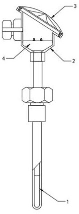
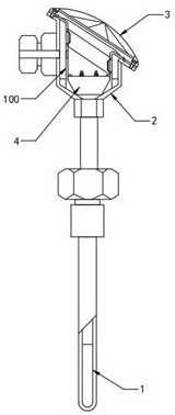
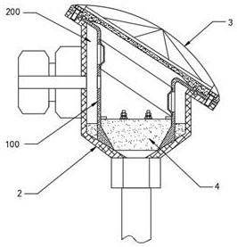
[0027] Such as Figure 1-3 As shown, an embodiment of the present invention proposes a manufacturing process of a multiple protection temperature sensor, the temperature sensor includes a temperature sensing probe 1, a flameproof member 100, a junction box 2 and a box cover 3, and the manufacturing process includes the following steps:

[0028] S1. Design a flameproof member 100 with a cylindrical structure including a pressure relief port 101, a ceramic sheet connecting piece 102 that is damaged and broken under the action of an external force, and a top end flange 103 that is sealed and connected inside the pressure relief port 101. Preparation Temperature probe 1, flameproof member 100, junction box 2 and box cover 3;

[0029] S2. Pre-install the flameproof part 100 in the junction box 2, form an outer flameproof cavity 200 between the flameproof part 100 and the inner wall of the junction box 2, and embed the electrician's seat 4 in the bottom of the inner cavity of the fl...


PUM


Abstract

The invention belongs to the technical field of temperature sensors, and particularly relates to a manufacturing process of a multi-protection temperature sensor. The temperature sensor comprises a temperature sensing probe, an explosion-proof member, a junction box and a box cover. The manufacturing process comprises the following steps: S1, designing the explosion-proof member, and preparing the temperature sensing probe, the explosion-proof member, the junction box and the box cover; S2, pre-arranging the explosion-proof member in the junction box, and forming an outer explosion-proof cavity between the explosion-proof member and the inner wall of the junction box; S3, filling the bottom end of the inner cavity of the outer explosion-proof cavity with a glue, so that the joint of the explosion-proof member and the junction box is sealed; and S4, clamping the top end connecting surface flange of the explosion-proof member between a junction box connecting surface flange and a box cover connecting surface flange. According to the invention, by designing the junction box structure with the explosion-proof member, the temperature of flames and jetted objects passing through the double explosion-proof joint surfaces is sharply reduced, so that the ignition temperature cannot be reached, the explosion-proof effect is better, a pressure relief function is achieved, multiple protection is effectively provided, the structure is simple, and the manufacturing cost is low.

Description

technical field [0001] The invention relates to the technical field of temperature sensors, in particular to a manufacturing process of a multi-protection temperature sensor. Background technique [0002] In order to meet the needs of use in high temperature and other environments, the junction box components with sufficient strength are designed using the principle of gap flameproof. The main structure of the existing explosion-proof flameproof temperature sensor is as follows: figure 1 As shown, it includes a temperature-sensing probe 1, a junction box 2, a box cover 3 and an electrician seat 4. The electrician seat 4 is arranged in the junction box 2. The temperature-sensing element in the temperature-sensing probe 1 is connected to the electrician seat 4 through a cable. The box cover 3 is joined to the top flange of junction box 2 and fastened by bolts. The principle of explosion-proof is: when the explosion in the shell spreads to the outside of the shell, the flame-p...

Claims


Application Information

Patent Timeline
IPC IPC(8): G01K1/08
CPCG01K1/08
Inventor 朱杰
Owner 宝应安的电子技术有限公司
Learn More