Biological detector for rapid detection

A detector and biological technology, which is applied to instruments, measuring devices, scientific instruments, etc., can solve the problems of being unable to be adsorbed upwards, and the bottom cannot be detached from the whole, so as to achieve the effect of smooth detection.

Inactive Publication Date: 2021-10-29
温诏伦
View PDF1 Cites 0 Cited by
  • Summary
  • Abstract
  • Description
  • Claims
  • Application Information

AI Technical Summary

Problems solved by technology

[0004] However, the existing technology only uses the suction force of the draft when taking food, and it may happen that a small piece of the bottom of the food detection cannot be separated from the whole, so that it cannot be absorbed upwards

Method used


Image

  • Biological detector for rapid detection
  • Biological detector for rapid detection
  • Biological detector for rapid detection

Examples


Embodiment 1

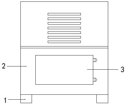
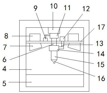
[0031] see Figure 1-2 , the present invention provides a technical solution for a rapid detection biological detector: its structure includes a base 1, a box body 2, a box door 3, a cavity 4, a placement seat 5, a fixed tube 6, a near-infrared emission cover 7, and a near-infrared spectrometer 8. Air pump 9, biological detector 10, observation room 11, motor 12, telescopic rod 13, sleeve 14, casing 15, suction head 16, partition 17, the bottom of the box 2 is provided with a base 1, the The box body 2 is provided with a cavity 4, the front of the cavity 4 is provided with a box door 3, the bottom of the cavity 4 is provided with a placement seat 5, and the biological detector 10 is connected to the top of the cavity 4, so The bottom of the biological detector 10 is connected to the observation chamber 11, the side of the observation chamber 11 communicates with the air pump 9 through a trachea, the bottom of the observation chamber 11 is connected to the top of the fixed pipe...

Embodiment 2

[0034] see Figure 1-8, the present invention provides a technical solution for a rapid detection biological detector: its structure includes a base 1, a box body 2, a box door 3, a cavity 4, a placement seat 5, a fixed tube 6, a near-infrared emission cover 7, and a near-infrared spectrometer 8. Air pump 9, biological detector 10, observation room 11, motor 12, telescopic rod 13, sleeve 14, casing 15, suction head 16, partition 17, the bottom of the box 2 is provided with a base 1, the The box body 2 is provided with a cavity 4, the front of the cavity 4 is provided with a box door 3, the bottom of the cavity 4 is provided with a placement seat 5, and the biological detector 10 is connected to the top of the cavity 4, so The bottom of the biological detector 10 is connected to the observation chamber 11, the side of the observation chamber 11 communicates with the air pump 9 through a trachea, the bottom of the observation chamber 11 is connected to the top of the fixed pipe ...


PUM


Abstract

The invention discloses a biological detector for rapid detection, which structurally comprises a base, a box body, a box door, a cavity, a placement base, a fixed pipe, a near infrared ray emission cover, a near infrared ray spectrometer, an air pump, a biological detector, an observation chamber, a motor, a telescopic rod, a sleeve, a sleeve pipe, a suction head and a partition plate, wherein the base is arranged at the bottom part of the box body, the cavity is formed in the box body, the box door is arranged in front of the cavity, the placement base is arranged at the bottom in the cavity, the biological detector is connected to the top part in the cavity, the bottom part of the biological detector is connected with the observation chamber, the side face of the observation chamber is communicated with the air pump through the air pipe, the bottom part of the observation chamber is connected with the top part of the fixing pipe, the middle of the fixing pipe penetrates through the partition plate, the bottom part of the fixing pipe is sleeved with the sleeve, the partition plate is connected into the cavity, and the bottom part of the sleeve is connected with the sleeve pipe. The biological detector has the beneficial effects that through cooperation of a starting structure and a cut-off device, food entering the suction head can be cut off, the food can be smoothly sucked upwards, and detection is smoother.

Description

technical field [0001] The invention relates to the technical field of food safety detection, in particular to a rapid detection biological detector. Background technique [0002] Food safety testing is to detect harmful substances in food according to national indicators, mainly the detection of some harmful and toxic indicators. Food safety issues have become a global topic. Vicious food safety incidents continue to occur internationally, causing huge economic losses. Food safety issues mainly include the following aspects: chemical hazards, biological toxins, microbial hazards, food safety testing, food adulteration and safety issues of genetically engineered foods; most of the existing food safety testing is done through product laboratories. Although the test results of the product laboratory are accurate and reliable, the cycle is long, the cost is high, and the operation is cumbersome, which cannot better meet people's needs. Therefore, a food safety test integrated w...

Claims


Application Information

Patent Timeline
Patent Type & Authority Applications(China)
IPC IPC(8): G01N21/359G01N21/01
CPCG01N21/359G01N21/01
Inventor 温诏伦
Owner 温诏伦
Why Eureka
Try Eureka