
Laser radar control method and device, electronic equipment and storage medium

A laser radar and control method technology, applied in radio wave measurement systems, instruments, etc., can solve the problems of unused and less point cloud data, and achieve the effect of clear point cloud data and accurate detection effect in the scanning area

Active Publication Date: 2021-10-29
ZVISION TECH CO LTD
View PDF4 Cites 3 Cited by
  • Summary
  • Abstract
  • Description
  • Claims
  • Application Information

AI Technical Summary

Problems solved by technology

The point cloud data obtained in the retrace area of ​​the lidar galvanometer is less, and the point cloud pattern is quite different from the pattern in the normal scan area. Therefore, there is usually no use for the retrace area.

Method used


Image

  • Laser radar control method and device, electronic equipment and storage medium
  • Laser radar control method and device, electronic equipment and storage medium
  • Laser radar control method and device, electronic equipment and storage medium

Examples


Embodiment Construction

[0066] The essence of the technical solutions of the embodiments of the present application will be explained in detail below in conjunction with the accompanying drawings.

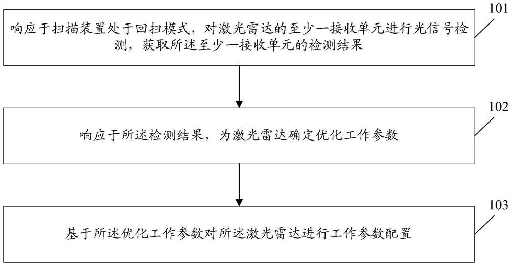
[0067] figure 1 It is a schematic flow chart of the radar control method of the embodiment of the present application, such as figure 1As shown, the radar control method of the embodiment of the present application includes the following steps:

[0068] Step 101 , in response to the fact that the scanning device is in the flyback mode, perform optical signal detection on at least one receiving unit of the laser radar, and obtain a detection result of the at least one receiving unit.

[0069] In the embodiment of the present application, the scanning device includes a mechanical vibrating mirror, a MEMS micro vibrating mirror, and the like. When the scanning device is in the retrace mode, the scanning device returns to the starting point of scanning from the deflected position.

[0070] In the embodimen...


PUM


Abstract

The invention discloses a laser radar control method and device, electronic equipment and a storage medium, and the method comprises the steps: carrying out the optical signal detection of at least one receiving unit of a laser radar in response to the condition that a scanning device is in a flyback mode, and obtaining a detection result of the at least one receiving unit; determining optimized working parameters for the laser radar in response to the detection result; and performing working parameter configuration on the laser radar based on the optimized working parameters. According to the invention, ambient light sensing is carried out in the flyback mode, and the working parameters of the laser radar are further optimized according to the ambient light sensing result, so that the point cloud data of the scanning area in the scanning mode is clearer, and the detection effect of the laser radar is more accurate.

Description

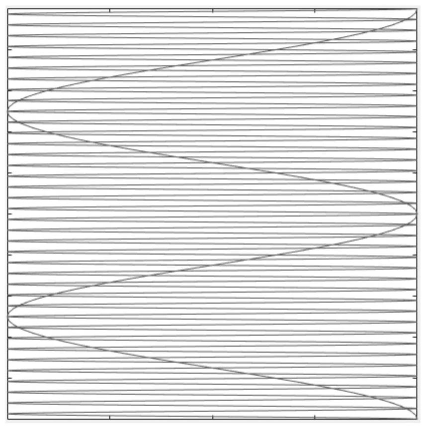
technical field [0001] The embodiments of the present application relate to lidar technology, and in particular, to a lidar control method and device, electronic equipment, and a storage medium. Background technique [0002] In laser radar, using the deflection of the galvanometer to realize the three-dimensional scanning of the laser in space is one of the main scanning methods. Wherein, the vibrating mirror includes a mechanical vibrating mirror, a microelectromechanical system (Microelectro Mechanical Systems, MEMS) micro vibrating mirror, and the like. Galvanometer scanning presents a closed scanning pattern in space and repeats the scanning periodically. The most common type of scanning graphics is row-column raster, and the obtained point cloud effect is intuitive and easy to use. The raster scanning pattern of the galvanometer can be divided into two parts: the normal scanning area and the retrace area. The retrace area is used to return the deflection position of t...

Claims


Application Information

Patent Timeline
Patent Type & Authority Applications(China)
IPC IPC(8): G01S7/48
CPCG01S7/48G01S7/4802Y02A90/10
Inventor 夏冰冰解华彪石拓
Owner ZVISION TECH CO LTD
Learn More