
Control circuit and display device of display panel

A technology for controlling circuits and display panels, applied in static indicators, instruments, etc., can solve the problems of high clock signal load and decreased operating stability of display panels, and achieve the effect of reducing production costs, reducing quantity, and reducing load

Active Publication Date: 2022-05-10
HKC CORP LTD
View PDF0 Cites 0 Cited by
  • Summary
  • Abstract
  • Description
  • Claims
  • Application Information

AI Technical Summary

Problems solved by technology

[0004] In view of this, an embodiment of the present application provides a control circuit and a display device for a display panel to solve the problem that as the size and resolution of the display panel continue to increase, the number of gate drive circuits for each display panel also continues to increase, resulting in The load of a single clock signal is too high, which reduces the stability of the display panel

Method used


Image

  • Control circuit and display device of display panel
  • Control circuit and display device of display panel
  • Control circuit and display device of display panel

Examples


Embodiment Construction

[0031] In the following description, specific details such as specific system structures and technologies are presented for the purpose of illustration rather than limitation, so as to thoroughly understand the embodiments of the present application. It will be apparent, however, to one skilled in the art that the present application may be practiced in other embodiments without these specific details. In other instances, detailed descriptions of well-known systems, devices, circuits, and methods are omitted so as not to obscure the description of the present application with unnecessary detail.

[0032] In addition, in the description of the specification and appended claims of the present application, the terms "first", "second", "third" and so on are only used to distinguish descriptions, and should not be understood as indicating or implying relative importance.

[0033] Reference to "one embodiment" or "some embodiments" or the like in the specification of the present app...


PUM


Abstract

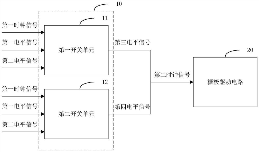
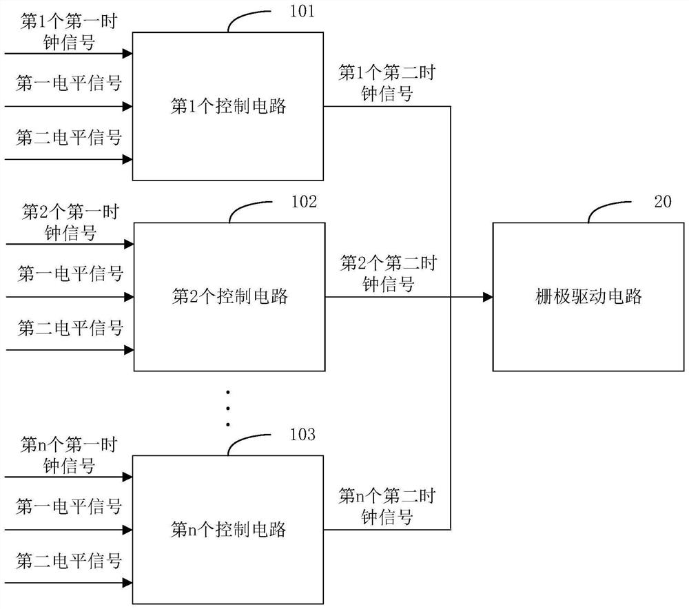
The present application is applicable to the field of display technology, and provides a control circuit of a display panel and a display device. The control circuit of the display panel in the embodiment of the present application is used to receive the first clock signal, the first level signal and the second level signal, and according to the first level signal and the second level signal, control the The first clock signal is phase-shifted to obtain the second clock signal and output to the gate drive circuit to realize the phase shift of the clock signal to reduce the load of a single clock signal, and can reduce the number of clock generators in the display panel and reduce the display Panel production costs.

Description

technical field [0001] The present application belongs to the field of display technology, and in particular relates to a control circuit of a display panel and a display device. Background technique [0002] With the rapid development of display technology, display panels are widely used in various fields such as entertainment, education, and security. GDL (Gate Driver Less, Array Substrate Row Drive) technology means that the gate driver IC (Gate driver IC) is directly fabricated on the array (Array) substrate, and the gate is scanned row by row by outputting row drive signals. The GDL technology can simplify the manufacturing process of the display panel, save the chip bonding process in the direction of the horizontal scanning line, and reduce the production cost. At the same time, it can improve the integration of the display panel and make the display panel lighter and thinner. [0003] Display panels using GDL technology need to use multiple clock signals to control ...

Claims


Application Information

Patent Timeline
Patent Type & Authority Patents(China)
IPC IPC(8): G09G3/20
CPCG09G3/20G09G2310/0267G09G3/3674G09G3/3266G09G2310/08
Inventor 沈婷婷康报虹
Owner HKC CORP LTD
Learn More