Antenna device with protection structure

A technology of antenna device and protective structure, which is applied in the direction of antenna support/installation device, etc., which can solve the problems of signal antenna without protective structure, easy damage in wind, inconvenient installation and disassembly of signal antenna and rod body, etc., to achieve convenient maintenance and Replacement operation, prevention of antenna damage, and the effect of being suitable for popularization

Pending Publication Date: 2021-10-29
深圳市三极技术有限公司
View PDF0 Cites 0 Cited by
  • Summary
  • Abstract
  • Description
  • Claims
  • Application Information

AI Technical Summary

Problems solved by technology

[0004] An antenna device with a protective structure proposed by the present invention solves the problem that the existing signal antenna and rod body are inconvenient to install and disassemble, and the signal antenna is not equipped with a protective structure and is easily damaged by wind

Method used


Image

  • Antenna device with protection structure
  • Antenna device with protection structure
  • Antenna device with protection structure

Examples


Embodiment 1

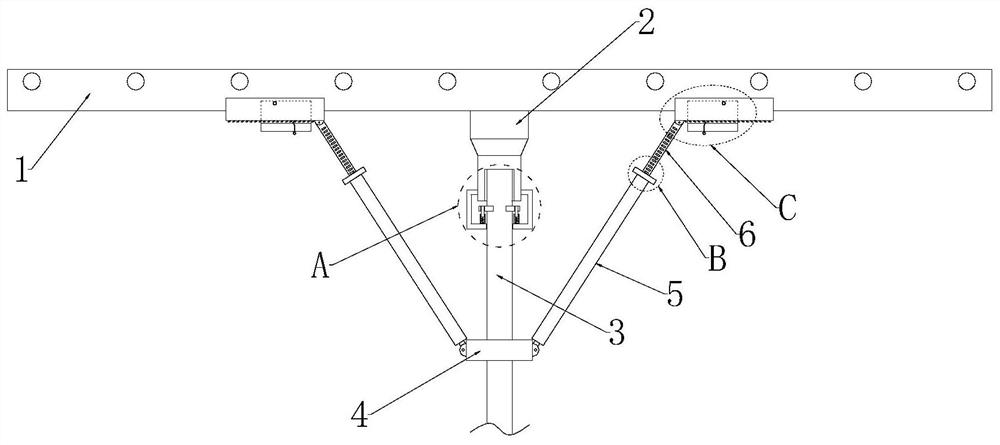
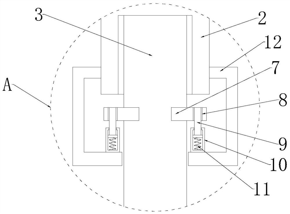
[0033] refer to Figure 1-3 , an antenna device with a protective structure, comprising an antenna main frame 1 and a rod body 3, the bottom end of the antenna main frame 1 is fixedly connected with a connecting sleeve 2, and the rod body 3 is sleeved on the bottom end of the connecting sleeve 2, and the connecting sleeve 2 A positioning mechanism is provided between the rod body 3;

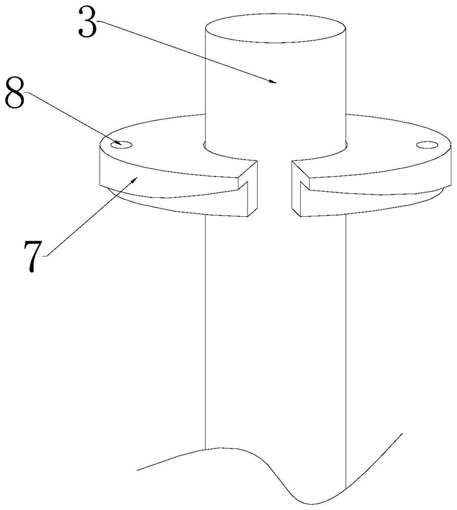
[0034] The positioning mechanism includes a positioning plate 7, a positioning hole 8, a positioning rod 9, a positioning sleeve 10, a positioning spring 11 and a connecting frame 12;

[0035] The circumferential side wall of the connecting sleeve 2 is fixedly connected with two symmetrically distributed connecting frames 12, the connecting frames 12 are arranged in a U-shaped structure, and the inner side of the connecting frame 12 is fixedly connected with a positioning sleeve 10, and the positioning sleeve The inner wall of the bottom end of 10 is fixedly connected with positioning spring 11,...

Embodiment 2

[0039] refer to figure 1 and Figure 4-9 In this embodiment, on the basis of Embodiment 1, a clamping mechanism is added to protect the main antenna frame 1 against wind. The wall is hinged with two symmetrically distributed first telescopic rods 5, the inner sliding sleeve of the first telescopic rod 5 is provided with a second telescopic rod 6, and a clamping mechanism is installed at the end of the second telescopic rod 6;

[0040] The clamping mechanism includes a movable plate 16, a mounting plate 17, a first hook 18, a movable rod 19, a second hook 20, a guide rod 21, a return spring 22, a draw ring 23, a chute 24, a slide block 25 and a splint 26.

[0041] The end of the first telescopic rod 5 away from the fixed plate 4 is rotatably mounted with a rotating disk 13, and the second telescopic rod 6 slides through the rotating disk 13, and the inner wall of the rotating disk 13 is fixedly connected with two engaging pieces 15 that are symmetrically distributed. Two sets...


PUM


Abstract

The invention discloses an antenna device with a protection structure, relates to the field of signal antennas, and provides the following scheme for solving problems that an existing signal antenna and a rod body are inconvenient to mount and dismount, and the signal antenna is not provided with a protection structure and is easily damaged when encountering wind: the antenna device comprises an antenna main frame and a rod body, and the bottom end of the antenna main frame is fixedly connected with a connecting sleeve; the rod body is arranged at the bottom end of the connecting sleeve in a sleeving mode, and a positioning mechanism is arranged between the connecting sleeve and the rod body. The circumferential side wall of the rod body is fixedly connected with a fixing plate in a sleeving mode, two symmetrically-distributed first telescopic rods are hinged to the circumferential side wall of the fixing plate, and second telescopic rods are slidably arranged in the first telescopic rods in a sleeving mode. The antenna device is novel in structure, the antenna main frame and the rod body of the antenna device are more convenient to mount and dismount compared with a traditional mode, the antenna can be conveniently overhauled and replaced, and the antenna can be effectively subjected to wind-resistant protection by arranging the clamping mechanism, so that the antenna is prevented from being damaged.

Description

technical field [0001] The invention relates to the field of signal antennas, in particular to an antenna device with a protective structure. Background technique [0002] An antenna is a transformer that transforms a guided wave propagating on a transmission line into an electromagnetic wave propagating in an unbounded medium, or vice versa. A component used in radio equipment to transmit or receive electromagnetic waves. Engineering systems such as radio communication, broadcasting, television, radar, navigation, electronic countermeasures, remote sensing, and radio astronomy, which use electromagnetic waves to transmit information, rely on antennas to work. In addition, in terms of transmitting energy with electromagnetic waves, non-signal energy radiation also requires antennas. Generally, antennas are reversible, that is, the same antenna can be used as both a transmitting antenna and a receiving antenna. [0003] The signal antenna of cable TV is generally installed...

Claims


Application Information

Patent Timeline
IPC IPC(8): H01Q1/12H01Q1/18
CPCH01Q1/12H01Q1/18
Inventor 周凯淦韦进黄烈云韩振宇刘华涛
Owner 深圳市三极技术有限公司
Why Eureka
Try Eureka