Eureka AIR delivers breakthrough ideas for toughest innovation challenges, trusted by R&D personnel around the world.

Charging circuit and electronic equipment

A technology for charging circuits and electronic equipment, applied to battery circuit devices, circuit devices, circuit monitoring/indication, etc., can solve the problem of low battery charging efficiency, achieve the effect of improving charging efficiency and avoiding power loss

Active Publication Date: 2021-10-29
上海泰矽微电子有限公司 +1
View PDF6 Cites 0 Cited by
  • Summary
  • Abstract
  • Description
  • Claims
  • Application Information

AI Technical Summary

Problems solved by technology

[0012] Aiming at the problem of low battery charging efficiency in the prior art, the present invention provides a charging circuit and electronic equipment, which help to improve charging efficiency

Method used


Image

  • Charging circuit and electronic equipment
  • Charging circuit and electronic equipment
  • Charging circuit and electronic equipment

Examples


Embodiment Construction

[0045] The technical solutions in the present invention will be described in further detail below in conjunction with the accompanying drawings.

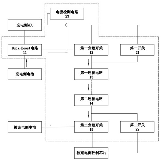
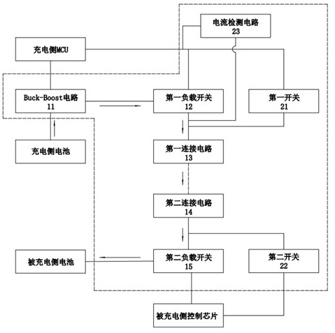
[0046] see figure 1 and figure 2 , is a charging circuit disclosed in the present invention, the charging circuit is composed of a Buck-Boost circuit 11, a first load switch 12, a first connection circuit 13, a second connection circuit 14 and a second load switch 15, etc., specifically , for the charging side, the input end of the Buck-Boost circuit 11 is used to connect to the battery on the charging side, the output end of the Buck-Boost circuit 11 is connected to the input end of the first load switch 12, and the output end of the first load switch 12 is connected to the first load switch 12. The input terminal of a connecting circuit 13 is connected.

[0047] For the charged side, the output end of the second connection circuit 14 is connected to the input end of the second load switch 15, and the output end of the second lo...


PUM


Abstract

The invention discloses a charging circuit and electronic equipment. The charging circuit comprises a Buck-Boost circuit, a first load switch, a first connecting circuit, a second connecting circuit and a second load switch; the input end of the Buck-Boost circuit is connected with a charging side battery; the input end of the first load switch is connected with the output end of the Buck-Boost circuit; the first connecting circuit is connected with the output end of the first load switch; the second connecting circuit is connected with the first connecting circuit; the input end of the second load switch is connected with the second connecting circuit; the output end of the second load switch is connected with a charged side battery; the Buck-Boost circuit and the control end of the first load switch are connected with a charging side MCU; the control end of the second load switch is connected with a charged side control chip; and when the first connecting circuit is connected with the second connecting circuit, the Buck-Boost circuit, the first load switch and the second load switch are switched into working states. The invention further provides electronic equipment comprising the charging circuit. According to the charging circuit and the electronic equipment disclosed by the invention, the charging efficiency can be improved.

Description

technical field [0001] The invention relates to the technical field of power supplies, in particular to a charging circuit and electronic equipment. Background technique [0002] Some batteries have limited capacity (such as wireless earphones), which requires that the charging current should not be too large. [0003] The commonly used solution is to control the charging current through a linear charging chip, but the conversion efficiency of this method is low. In order to solve this problem, there are methods on the market that use communication methods to improve conversion efficiency, but frequent communication will increase the charging time. The following are several existing charging methods: [0004] The first charging method uses a linear charging chip for charging. The conversion efficiency of the charged side (such as earphones) is as follows: [0005] [0006] In the formula: Vbat is the voltage of the battery on the charged side; V in is the access voltag...

Claims


Application Information

Patent Timeline
Patent Type & Authority Applications(China)
IPC IPC(8): H02J7/00H02H7/18
CPCH02J7/007182H02J7/00714H02J7/00716H02J7/00304H02J7/0048H02J7/0049H02H7/18Y02B40/00
Inventor 丁德彬陈立新熊海峰
Owner 上海泰矽微电子有限公司
Why Eureka
Eureka Blog
Learn More