Hollow turbine blade

一种透平叶片、叶型的技术,应用在叶片的支承元件、发动机元件、机器/发动机等方向

Inactive Publication Date: 2007-03-28
SIEMENS AG
View PDF1 Cites 16 Cited by
  • Summary
  • Abstract
  • Description
  • Claims
  • Application Information

AI Technical Summary

Problems solved by technology

[0003] However, it has been shown that, viewed in the flow direction of the hot gases, cracks can also develop behind the slit, ie in the middle region of the blade profile

Method used


Image

  • Hollow turbine blade
  • Hollow turbine blade

Examples


Embodiment Construction

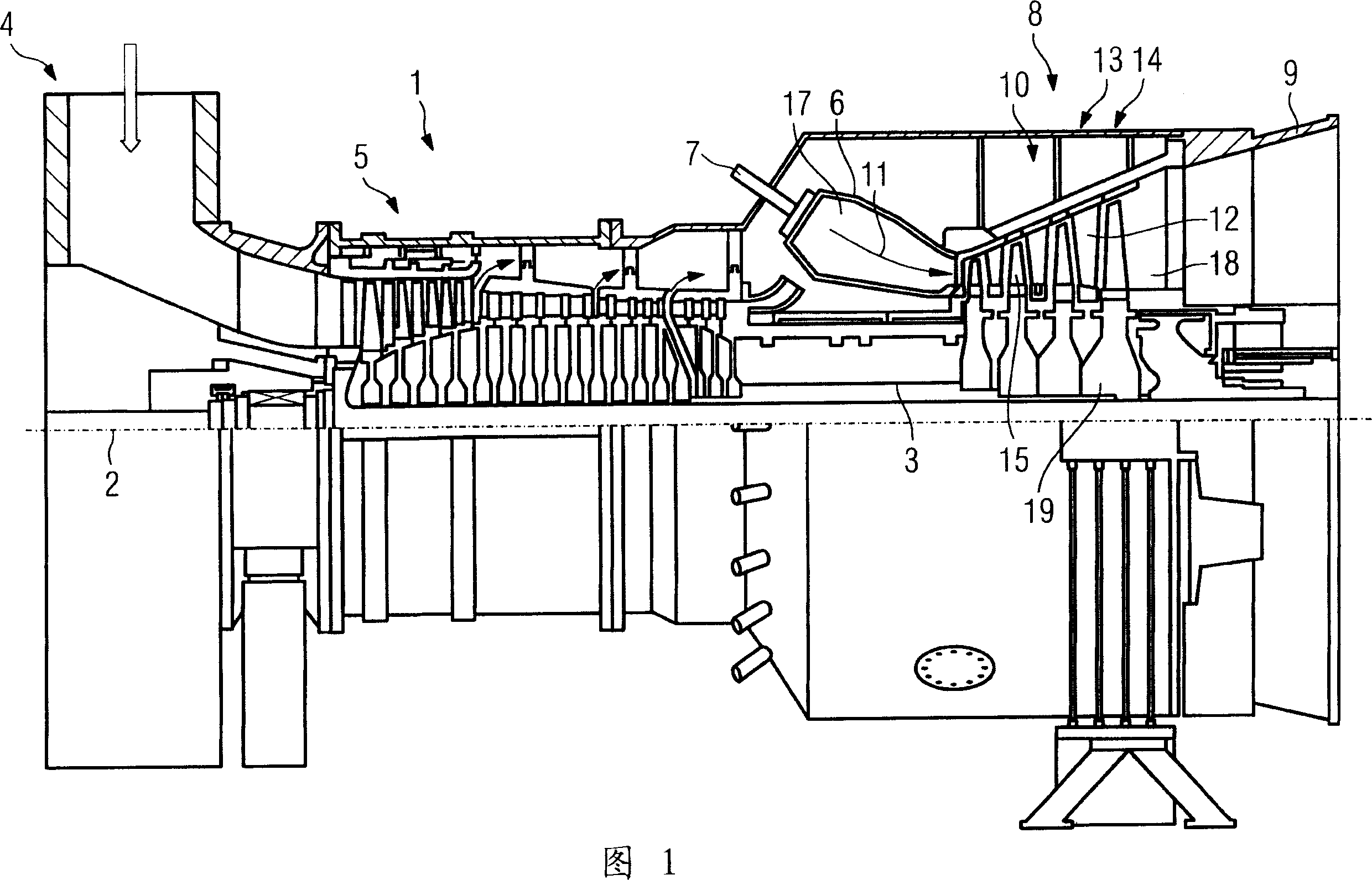
[0016] FIG. 1 shows a gas turbine 1 in a longitudinal partial section. The gas turbine internally has a rotor 3 mounted rotatably about an axis of rotation 2 , which is also referred to as a turbine rotor. Along the rotor 3 there are successively a suction housing 4 , a compressor 5 , an annular combustion chamber 6 with a plurality of burners 7 arranged rotationally symmetrically to one another, a turbine unit 8 and an outlet housing 9 . The annular combustion chamber 6 forms a combustion chamber 17 which communicates with an annular hot gas channel 18 . Here, four successively connected turbine stages 10 form the turbine unit 8 . Each turbine stage 10 consists of two blade rings. Viewed along the flow direction of the hot gas 11 generated in the annular combustion chamber 6 , each guide vane group 12 is followed by a respective rotor blade group 14 formed of rotor blades 15 in the hot gas channel 18 . The guide vanes 12 are attached to the stator, while the rotor blades 1...


PUM


Abstract

This hollow turbine blade comprises airfoil bodies 36 formed on the rear wall 42 of the blade and the front wall 44 of the blade and washed down by combustion gas 11, at least one partition wall 48 formed inside a turbine blade 30, and the at least one slit 56 formed on the combustion gas side of the blade walls 42, 44 and extending along the blade axis. The airfoil bodies comprise a height H equal to a distance between a blade pedestal 32 and an airfoil body end 58 measured along the blade axis. The partition wall joints the rear wall 42 of the blade to the front wall 44 of the blade at the joined portion 50. The slits 56, 62 are positioned in the blade walls 42, 44 on the combustion gas side to face the joined portion 50 formed of the partition wall 48 and the blade walls 42, 44.

Description

technical field [0001] The invention relates to a hollow turbine blade having a bearing surface airfoil formed by a suction side airfoil wall and a pressure side airfoil wall which can be circulated by hot gas, the bearing surface airfoil extending from the platform to the airfoil apex Having a profile height along the blade axis, the hollow turbine blade also has at least one support rib arranged inside the turbine blade and at least one rib arranged on the hot gas side in the profile wall and extending along the blade axis. The support ribs connect the pressure-side airfoil wall to the suction-side airfoil wall in the respective connecting region. Furthermore, the invention also relates to the use of the aforementioned turbine blade. Background technique [0002] EP 1 508 399 A1 discloses a turbine blade for a gas turbine, which spatially limits the growth of cracks caused by slits running in the region of the blade leading edge, so that impermissibly large cracks are pre...

Claims


Application Information

Patent Timeline
Patent Type & Authority Applications(China)
IPC IPC(8): F01D5/14
CPCF01D5/16F01D5/147
Inventor 法蒂·阿迈德迈克·丹克特
Owner SIEMENS AG
Why Eureka
Try Eureka