Dangerous rock blasting hole tree root removing device

A technology for clearing devices and dangerous rock masses, which is applied in the fields of application, agriculture, forestry, etc. It can solve problems such as hidden safety hazards, affecting blasting effects, and tree roots affecting drilling, etc., and achieves the advantages of convenient operation, improved operational safety, and improved results. Effect

Active Publication Date: 2021-11-02
ANHUI UNIV OF SCI & TECH
View PDF11 Cites 0 Cited by
  • Summary
  • Abstract
  • Description
  • Claims
  • Application Information

AI Technical Summary

Problems solved by technology

[0002] Dangerous rock mass means that when the rock mass is suspended and has obvious cracks, there is a risk of collapse at any time, so it has a major safety hazard. Because the terrain of the dangerous rock mass is relatively complicated, most of them are on uneven slopes and cliffs. Therefore, blasting is usually used to remove the dangerous rock mass. Since trees, vines and other plants usually grow around the dangerous rock mass and on the body, the roots of the plants will drill into the cracks of the dangerous rock mass, and the tree roots will affect the drilling. , and when the emulsion explosive is loaded into the blast hole, it will be stuck, and the explosive will not be filled at the bottom of the hole, which will seriously affect the blasting effect. Therefore, we propose a device for removing tree roots in the blast hole of dangerous rock

Method used


Image

  • Dangerous rock blasting hole tree root removing device
  • Dangerous rock blasting hole tree root removing device
  • Dangerous rock blasting hole tree root removing device

Examples


Embodiment Construction

[0020] The following will clearly and completely describe the technical solutions in the embodiments of the present invention with reference to the accompanying drawings in the embodiments of the present invention. Obviously, the described embodiments are only some, not all, embodiments of the present invention. Based on the embodiments of the present invention, all other embodiments obtained by persons of ordinary skill in the art without creative efforts fall within the protection scope of the present invention.

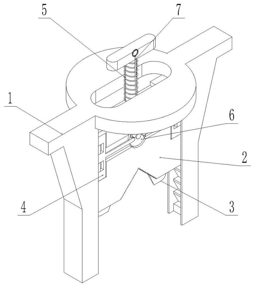
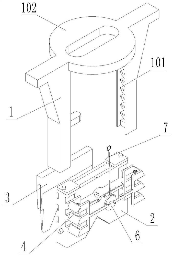
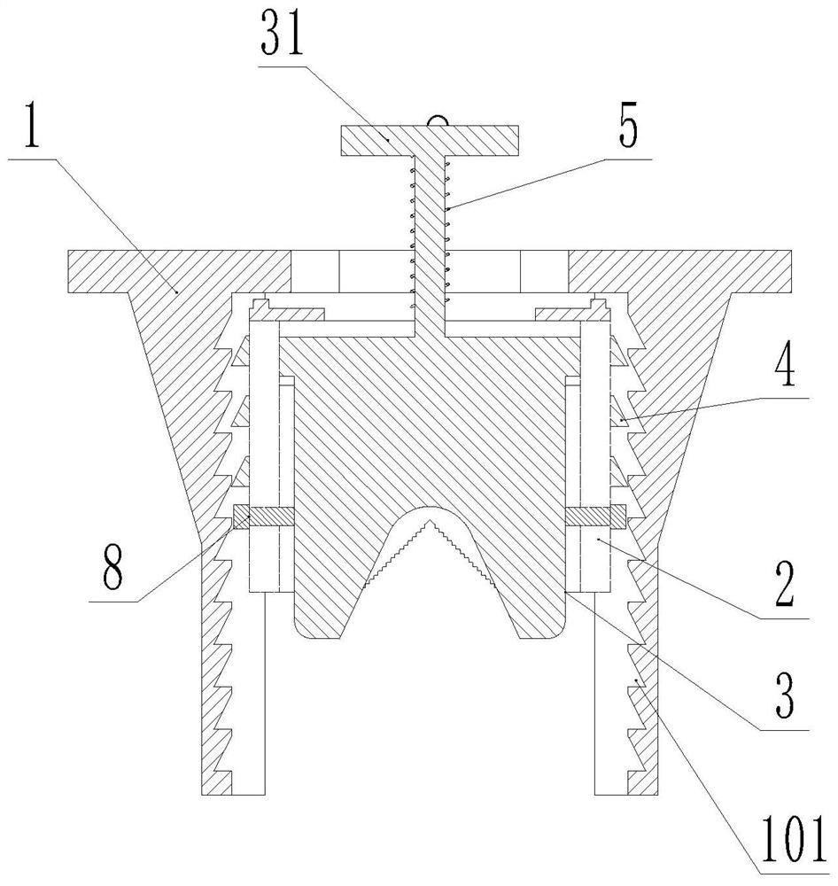
[0021] see Figure 1 to Figure 6 As shown, a root removal device for blasting blastholes in dangerous rock mass, including a chopping knife 3, the bottom end of the chopping knife 3 is provided with an arc-shaped knife edge 33, and the chopping knife 3 is accommodated in the fixing seat 2 and is slidably connected with the fixing seat 2, and fixed The two ends of the seat 2 are stored in the chute opened by the poles on both sides of the fixed support 1, the fixed ...


PUM


Abstract

Dangerous rock blasting hole tree root removing device The invention discloses a dangerous rock blasting hole tree root removing device, and belongs to the technical field of blasting engineering. The dangerous rock blasting hole tree root removing device comprises a cutting die, an arc-shaped cutting edge is arranged at the bottom end of the cutting die, the cutting die is contained in a fixing base and is in sliding connection with the fixing base, the two end sides of the fixing base are contained in sliding grooves formed in supporting rods on the two sides of a fixing support, the fixing base is movably connected with the fixing support, a clamping mechanism is arranged between the fixing base and the fixing support and used for fixing the fixing base and the fixing support, a connecting rod is arranged at the top end of the cutting die, a stress plate is arranged at the top end of the connecting rod, the connecting rod is detachably connected with the stress plate, a first spring is arranged between the bottom end of the stress plate and the top end of the fixing base, a limiting plate is arranged at the top end of the fixing base to prevent the cutting die from falling out of the fixing base; the connecting rod at the top of the cutting die can be detached to a plurality of connecting rods, the connecting rods is connected in a threaded mode, according to the dangerous rock blasting hole tree root removing device, the cutting die is arranged in the fixing base, a tool is used for knocking the cutting die to cut off tree roots, operation is convenient, and operation safety is improved.

Description

technical field [0001] The invention belongs to the technical field of blasting engineering, and in particular relates to a tree root removal device for blasting blastholes in dangerous rock masses. Background technique [0002] Dangerous rock mass means that when the rock mass is suspended and has obvious cracks, there is a risk of collapse at any time, so it has a major safety hazard. Because the terrain of the dangerous rock mass is relatively complicated, most of them are on uneven slopes and cliffs. Therefore, blasting is usually used to remove the dangerous rock mass. Since trees, vines and other plants usually grow around the dangerous rock mass and on the body, the roots of the plants will drill into the cracks of the dangerous rock mass, and the tree roots will affect the drilling. , and when the emulsion explosive is loaded into the blasthole, it will be stuck, and the explosive will not be filled at the bottom of the hole, which will seriously affect the blasting ...

Claims


Application Information

Patent Timeline
Patent Type & Authority Applications(China)
IPC IPC(8): A01G23/06
CPCA01G23/06
Inventor 尹涛郭子如李洪伟何志伟
Owner ANHUI UNIV OF SCI & TECH
Why Eureka
Try Eureka