Plate-and-frame driving mechanism and plate-and-frame filter pressing device

A driving mechanism, plate and frame technology, applied in the direction of filtration and separation, separation methods, chemical instruments and methods, etc., can solve problems such as air or oil leakage of driving cylinders or oil cylinders, affecting normal operation of equipment, and corroding piston rods, etc., to achieve Smooth flow, reduced processing cost, and extended service life

Pending Publication Date: 2021-11-02
无锡方大环保科技有限公司
View PDF0 Cites 0 Cited by
  • Summary
  • Abstract
  • Description
  • Claims
  • Application Information

AI Technical Summary

Problems solved by technology

[0002] Plate and frame filter press is the first machine used in chemical dehydration. It has the advantages of large filtration driving force, high solid content of filter cake, clear filtrate, high solid recovery rate, and less consumption of conditioning chemicals. Plate and frame filter press Including the push plate and the pressure plate, the push plate and the pressure plate need to be opened and closed. The traditional plate and frame filter press installs the drive cylinder or oil cylinder on the pressure plate, and then connects the piston rod of the drive cylinder or oil cylinder to the push plate. The pressure plate is connected, and the piston rod is extended or retracted by driving the cylinder or oil cylinder, so as to realize the opening or closing of the pushing plate and the pressure receiving plate. However, some materials processed are corrosive and will corrode the piston rod. Since the piston rod and the cylinder body of the driving cylinder or oil cylinder directly need to be provided with sealing parts, and once the piston rod is corroded, it is easy to damage the sealing structure, resulting in air or oil leakage from the driving cylinder or oil cylinder, affecting the normal operation of the equipment. Increased maintenance frequency and high maintenance costs

Method used


Image

  • Plate-and-frame driving mechanism and plate-and-frame filter pressing device
  • Plate-and-frame driving mechanism and plate-and-frame filter pressing device
  • Plate-and-frame driving mechanism and plate-and-frame filter pressing device

Examples


Embodiment 1

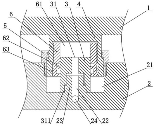
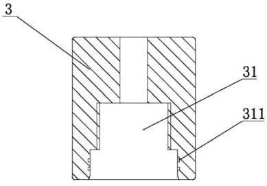
[0054] like Figure 1 to Figure 7 As shown, the plate and frame driving mechanism of the present embodiment includes a pushing plate 1 and a pressure bearing plate 2, and several housing piston spaces 21 for installing the driving mechanism are provided around the pressure bearing plate 2, and the upper end of the housing piston space 21 is connected to the gland 5 . The driving mechanism includes a piston rod 3, a guide sleeve 6 and a housing 4. The housing 4 is processed with internal threads, and the outer side of the matching guide sleeve 6 is processed with external threads. The guide sleeve 6 is threadedly connected to the housing 4 through internal threads and external threads. Inside, the piston rod 3 passes through the guide hole 61 provided in the guide sleeve 6, and the inner and outer sides of the guide sleeve 6 are respectively provided with an inner seal groove 62 and an outer seal groove 63, and the seal between the piston rod 3 and the guide sleeve 6 is install...

Embodiment 2

[0057] like Figure 8 , Figure 9 As shown, the housing 4 and the guide sleeve 6 can also be integrally connected, the housing 4 and the guide sleeve 6 can further reduce the installation space, and there is no need to process the outer sealing groove 63, and the third sealing ring is not used, further reducing the production cost.

[0058] The outside of the housing 4 can be coated with corrosion-resistant materials, which can improve the corrosion resistance of the housing 4 .

[0059] The pressure can be hydraulic oil or high pressure gas.

[0060] When the plate and frame driving mechanism of this embodiment is installed, the piston rod 3 is first screwed to the boss 23 of the housing piston space 21 of the pressure bearing plate 2, and then the guide sleeve 6 is screwed into the housing 4, and the connection is completed. Then the guide sleeve 6 and the housing 4 are sleeved and connected to the outside of the piston rod 3, and finally the gland 5 is connected to the pi...

Embodiment 3

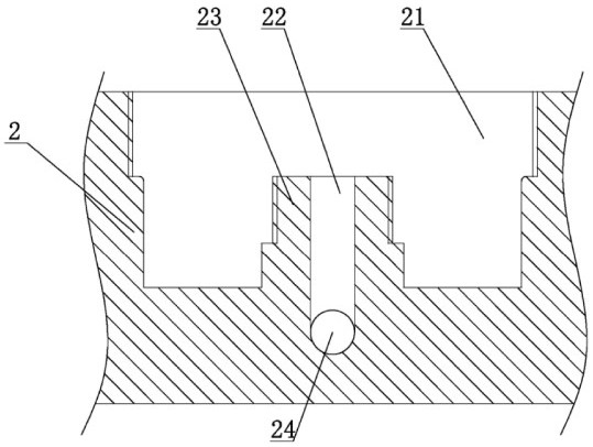
[0062] like Figure 10 As shown, in another embodiment, the boss 23 of the pressure bearing plate 2 may not be provided with an external thread, but an internal thread may be provided in the pressure medium passage 22, and after the piston rod 3 is inserted into the boss 23 , by tightening the hollow bolt 7 into the pressure medium passage 22 to realize the fixed connection between the piston rod 3 and the boss 23; The piston rod 3 and the boss 23 are connected and fixed by the hollow bolt 7, which can reduce the processing difficulty of the pressure bearing plate 2 and reduce the processing cost.

[0063] like Figure 11 As shown, in another embodiment, the housing 4 may not be provided with the guide sleeve 6 , and the housing 4 is directly sleeved on the outside of the piston rod 3 . The outer circumference of the lower part of the housing 4 can also be provided with an outer ring groove 41, and an outer support ring 8 is arranged in the outer ring groove 41, which can im...


PUM


Abstract

The invention discloses a plate-and-frame driving mechanism and a plate-and-frame filter pressing device. A plurality of shell piston spaces are formed in a bearing plate, piston rods are fixed in the shell piston spaces, through holes are formed in the piston rods, and the through holes are communicated with a pressure medium pipeline. The piston rods are sleeved with a shell, an inner cavity of the shell is communicated with the through holes, and the shell is limited through glands at the openings of the shell piston spaces. During work, the top face of the shell makes contact with the bottom face of a pushing and pressing plate and acts on the pushing and pressing plate. The piston rods are connected in the shell piston spaces of the bearing plate, a pressure medium enters the shell to push the shell to move, and the shell moves to push the pushing and pressing plate to be far away from or close to the bearing plate. When the device is used, the piston rods are sealed in the shell, not exposed outside and not corroded, the service life of an oil cylinder is prolonged, the maintenance frequency is reduced, and the maintenance cost is saved.

Description

technical field [0001] The invention relates to filter press equipment, in particular to a plate and frame drive mechanism and a plate and frame filter press device. Background technique [0002] Plate and frame filter press is the first machine used in chemical dehydration. It has the advantages of large filtration driving force, high solid content of filter cake, clear filtrate, high solid recovery rate, and less consumption of conditioning chemicals. Plate and frame filter press Including the push plate and the pressure plate, the push plate and the pressure plate need to be opened and closed. The traditional plate and frame filter press installs the drive cylinder or oil cylinder on the pressure plate, and then connects the piston rod of the drive cylinder or oil cylinder to the push plate. The pressure plate is connected, and the piston rod is extended or retracted by driving the cylinder or oil cylinder, so as to realize the opening or closing of the pushing plate and ...

Claims


Application Information

Patent Timeline
Patent Type & Authority Applications(China)
IPC IPC(8): B01D25/21
CPCB01D25/21
Inventor 过曙昉
Owner 无锡方大环保科技有限公司
Why Eureka
Try Eureka