A tail gas recovery device for liquid chemicals
A technology of exhaust gas recovery and chemicals, applied in gas collection devices and other directions, can solve problems such as waste of resources and air pollution, and achieve the effect of saving manpower
- Summary
- Abstract
- Description
- Claims
- Application Information
AI Technical Summary
Problems solved by technology
Method used
Image

Examples
Embodiment 1
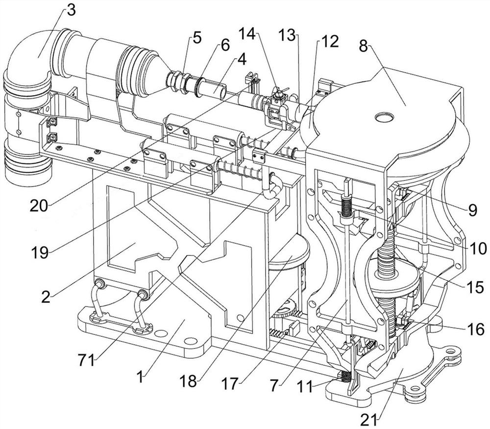
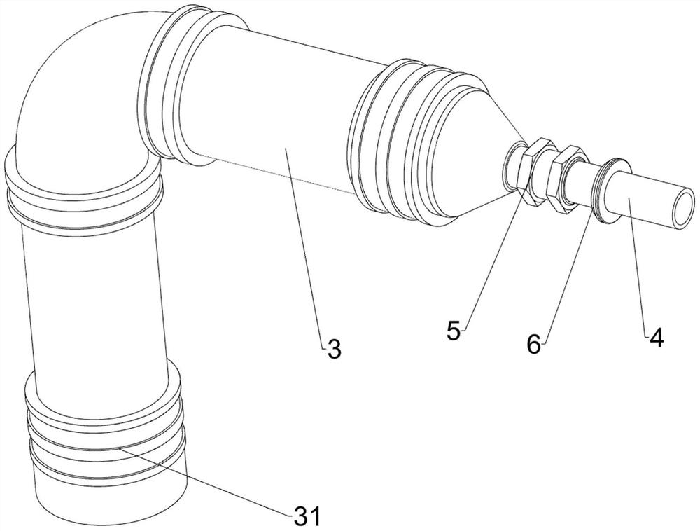
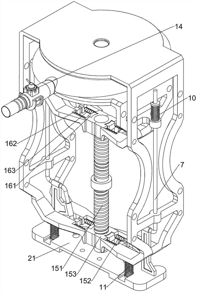
[0038] A tail gas recovery unit for liquid chemicals such as figure 1 , figure 2 , image 3 , Figure 4 , Figure 5 , Image 6 , Figure 14 and Figure 15 As shown, it includes a bottom plate 1, a mounting frame 2, a slide plate 21, an air guide pipe 3, a joint 31, an air outlet pipe 4, a one-way valve 5, a rubber ring 6, a guide rail 7, a guide rod 71, a first sliding frame 8, and a second sliding frame. The sliding frame 9, the first tension spring 10, the second tension spring 11, the air bag 12, the connecting pipe 13, the air valve 14, the lifting assembly 15 and the extrusion assembly 16, the top left side of the bottom plate 1 is connected with the mounting frame 2, the bottom plate 1. The slide plate 21 is slidably connected on the right side, the air duct 3 is connected to the left side of the top of the mounting frame 2, the joint 31 is connected to the lower left part of the air duct 3, the air outlet pipe 4 is connected to the right side of the air duct 3, a...
Embodiment 2
[0043] On the basis of Example 1, as figure 1 and Figure 7-9 As shown, it also includes an adsorption assembly 17, and the adsorption assembly 17 includes a first connecting plate 171, a rack 172, a driving motor 173, a shaft 174, a gear 175, a second iron block 176, a second electromagnet 177 and a return spring 178, a first connecting plate 171 is connected to the left side of the top of the slide plate 21, a rack 172 is connected to the front and rear sides of the top of the first connecting plate 171, and a drive motor 173 is installed on the lower part of the rear side of the mounting frame 2, and the output shaft of the drive motor 173 A shaft 174 is connected, the front and rear sides of the shaft 174 are connected with gears 175, the gears 175 are meshed with the racks 172, the right side of the first connecting plate 171 is connected with a second iron block 176, and the middle of the top of the bottom plate 1 is connected with a second iron block 176. Two electroma...
Embodiment 3
[0049] On the basis of Example 2, as figure 1 and Figure 9-10 As shown, it also includes a positioning assembly 19. The positioning assembly 19 includes an arc-shaped block 192, a second connecting plate 193, an arc-shaped positioning plate 194 and an elastic clamping plate 195. The bottom of the connecting pipe 13 is connected with an arc-shaped block 192. Two guide rails A second connecting plate 193 is connected between the left sides, an arc-shaped positioning plate 194 is connected to the second connecting plate 193, and an elastic splint 195 is connected to the left of the arc-shaped positioning plate 194.
[0050] When the airbag 12 is placed, the connecting tube 13 can be placed between the arc-shaped positioning plate 194 and the elastic splint 195 to position the connecting tube 13 .
[0051] like figure 1 and Figure 11-13 As shown, it also includes an opening and closing assembly 20. The opening and closing assembly 20 includes a third connecting plate 201, a g...
PUM
 Abstract
Description
Claims
Application Information
 - R&D
- Intellectual Property
- Life Sciences
- Materials
- Tech Scout
- Unparalleled Data Quality
- Higher Quality Content
- 60% Fewer Hallucinations
Browse by: Latest US Patents, China's latest patents, Technical Efficacy Thesaurus, Application Domain, Technology Topic, Popular Technical Reports.
© 2025 PatSnap. All rights reserved.Legal|Privacy policy|Modern Slavery Act Transparency Statement|Sitemap|About US| Contact US: help@patsnap.com