Smart home LED lamp

A LED lamp and smart home technology, applied in lighting and heating equipment, semiconductor devices of light-emitting elements, lighting devices, etc., can solve the problems of complicated process of replacing light strips, time-consuming and labor-intensive use of tools, etc., to increase the lighting effect , maintenance work is simple, and the effect of improving practicability

Inactive Publication Date: 2021-11-02
赵俊
View PDF0 Cites 0 Cited by
  • Summary
  • Abstract
  • Description
  • Claims
  • Application Information

AI Technical Summary

Problems solved by technology

[0005] In view of the fact that all the light strips inside the existing smart home LED lights in the prior art are connected to the circuit, the light strips will be damaged due to various reasons during long-term use, and the light strips need to be replaced. When replacing, First go out to buy the specified light strip, then disconnect the lighting power supply, then move the ladder to climb to a high place to disassemble the LED light, then use tools to separate the bad light strip from the circuit, and then use tools to disassemble the light strip, Then fix the purchased light bar at the position where the bad light bar was before, then connect the light bar to the circuit, and then install the LED light shell to complete the work of replacing the light bar, but it takes a lot of time to buy a specified light bar when going out. It takes a long time, time-consuming and labor-intensive, and the lighting power needs to be disconnected before replacing the light bar, which affects the normal use of other lamps in the home. At the same time, the process of replacing the light bar is not only complicated, but also requires many tools. It is also extremely dangerous, resulting in later maintenance work Extremely difficult problem, the purpose of the present invention is to provide a smart home LED lamp, which can well solve the problems raised in the background technology

Method used


Image

  • Smart home LED lamp
  • Smart home LED lamp
  • Smart home LED lamp

Examples


Embodiment Construction

[0038] The technical solutions in the embodiments of the present invention will be clearly and completely described below in conjunction with the accompanying drawings in the embodiments of the present invention; obviously, the described embodiments are only some embodiments of the present invention; rather than all embodiments. Based on the embodiments of the present invention; all other embodiments obtained by persons of ordinary skill in the art without creative work; all belong to the protection scope of the present invention.

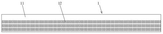
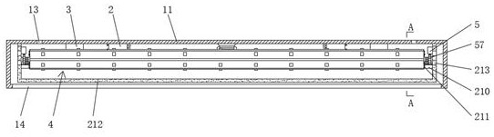
[0039] see Figure 1-16 , a smart home LED lamp, comprising a decorative main body 1, and a fixing device 2 is arranged inside the decorative main body 1.

[0040] The decorative main body 1 includes a decorative box 11, the surface of the decorative box 11 is provided with a decorative hole 12, the top surface of the decorative box 11 is provided with a fixing hole 13, and the top surface of the decorative box 11 is also provided with a threading ...


PUM


Abstract

The invention discloses a smart home LED lamp which comprises a decoration body, and a fixing device is arranged in the decoration body. Through a power-on and power-off device, the electric connection relation between the LED lamp and the lighting power source is automatically disconnected after a light uniformizing cover moves downwards by a certain distance, and the lighting power source does not need to be turned off, so that it is ensured that other lamps are not affected in the process that people replace the fixed lamp strips; standby fixed lamp strips are temporarily stored through a storage device, so that people do not need to purchase the fixed light strips when the fixed light stripsare damaged, and time and labor are saved; through cooperation of the storage device, a limiting device and a conductive device, people can quickly connect the standby fixed light strips into a circuit, and tools are not needed; people can quickly mount and dismount the fixed light strips through a replacement device, so that latermaintenance is simple, convenient and fast; and the LED lamp beads connected into the circuit face the right lower portion through the limiting device, so that the lighting effect is improved, and the practicability of the intelligent LED lamp is improved.

Description

technical field [0001] The present invention relates to the field of LED lamps, more specifically, to a smart home LED lamp. Background technique [0002] The LED lamp is an electroluminescent semiconductor material chip, which is cured on the bracket with silver glue or white glue, and then connected to the chip and the circuit board with silver or gold wires, and sealed with epoxy resin around it to protect the inner core wire. Function, finally install the shell, so the LED lamp has good shock resistance, and the LED lamp can directly emit red, yellow, blue, green, blue, orange, purple, white light, which has energy saving, longevity, environmental protection, small size and strong applicability , no stroboscopic, safe and reliable, etc., the inherent characteristics of LED lights determine that it is the most ideal light source to replace traditional light sources, so LED lights are widely used in the field of home furnishing. With the development of technology and the e...

Claims


Application Information

Patent Timeline
IPC IPC(8): F21S8/04F21V21/38F21V23/04F21V33/00F21V19/00F21V23/06F21Y115/10
CPCF21S8/04F21V21/38F21V23/04F21V33/00F21V19/0015F21V23/06F21Y2115/10
Inventor 赵俊
Owner 赵俊
Why Eureka
Try Eureka