Check patentability & draft patents in minutes with Patsnap Eureka AI!

Aircraft, operation method thereof and flight control system

A flight control system and aircraft technology, applied in the field of operating aircraft, can solve problems such as inability to ensure, and achieve an easy-to-achieve effect

Pending Publication Date: 2021-11-02
沃科波特有限公司
View PDF3 Cites 0 Cited by
  • Summary
  • Abstract
  • Description
  • Claims
  • Application Information

AI Technical Summary

Problems solved by technology

But this does not ensure that the calculated motor command is also "feasible" (i.e. achievable), for example, in the case of rotorcraft, that is to say, for example, that the RPM (speed of rotation) limits of the rotor are respected

Method used


Image

  • Aircraft, operation method thereof and flight control system
  • Aircraft, operation method thereof and flight control system

Examples


Embodiment Construction

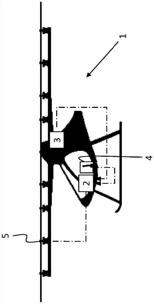
[0039] exist figure 1 In , an aircraft in the form of a manned multirotor aircraft with a plurality of drive units is schematically shown at reference number 1 . In particular, it concerns an aircraft known per se produced by the Applicant, which has 18 drive units (rotors with corresponding drive motors). But the present disclosure is not limited to such aircraft. For example, the aircraft may also have so-called propellers (for acceleration in the forward direction) in addition to the illustrated raising rotors. The specific technical design of the drive unit used has at least no major role within the scope of the present disclosure.

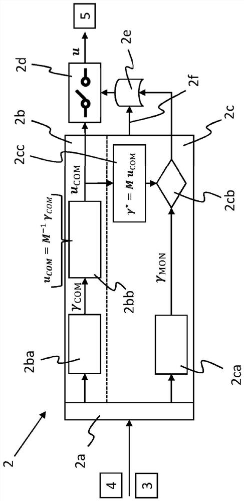
[0040] The aircraft 1 has a flight control system indicated at 2 , which will be explained in more detail below. The reference numeral 3 designates a sensor device which provides corresponding measurement results or sensor (measurement) results for describing the (actual) state of the aircraft 1 . As shown, the sensor device 3 is in signal...


PUM


Abstract

The present disclosure relates to an aircraft having N drive units, where N > 4, preferably in the form of electrically driven rotors, and a method of operation and a flight control system thereof; the flight control system generating control commands uCOM for the drive units via a first channel and transmitting the control commands to the drive units, U being a boundary of the drive units. The flight control system also generates, in the first channel, a pseudo control command [gamma] COM giving the torque and thrust generated by the drive unit about the respective axis of rotation of the aircraft, wherein [gamma] COM belongs to R4. The control matrix M belongs to R4 * N establishes a relationship with the control command u according to gamma = M u, and an allowable control command uCOM belongs to U is calculated by the pseudo control command gamma COM through a distribution algorithm in the first channel; the first channel is monitored by an independent second channel and passivated according to the monitoring result. A pseudo control instruction gamma MON is also generated in the second channel, and gamma MON belongs to R4; and the control command uCOM of the first channel is evaluated using the relationship gamma * = M uCOM, i.e., gamma * is compared with gamma MON to produce a monitoring result to monitor the first channel in the second channel.

Description

technical field [0001] The present disclosure relates to a method for operating an aircraft having N drive units, N>4, preferably in the form of electrically driven rotors, in which method the flight control system via a first One channel generates control commands for the drive unit And transmit the control command to the drive unit, U represents the (technical or physical) boundary of the drive unit; the flight control system also generates pseudo control commands in the first channel The pseudo-control instructions give the torque and thrust about the corresponding rotation axis of the aircraft, the torque and the thrust are generated by the drive unit, wherein the control matrix M∈R 4×N is to establish the relationship with the control command u according to γ=Mu, in the first channel, through the allocation algorithm according to the pseudo control command γ MON Calculate the allowable control instruction u COM ∈U, the first channel is monitored by an independent ...

Claims


Application Information

Patent Timeline
IPC IPC(8): G05D1/10
CPCG05D1/101B64C27/08G05D1/0077B64D27/24B64D31/06Y02T50/60G05D1/0055B64D31/04B64D31/14
Inventor J·斯蒂芬J·兹维纳
Owner 沃科波特有限公司
Features
  • R&D
  • Intellectual Property
  • Life Sciences
  • Materials
  • Tech Scout
  • Unparalleled Data Quality
  • Higher Quality Content
  • 60% Fewer Hallucinations
Learn More