
Off-line assembling device for multi-roll-core lithium battery

A technology for assembling devices and lithium batteries, which is applied in the directions of feeding devices, positioning devices, storage devices, etc., can solve problems such as inconvenience in battery assembly, and achieve the effects of simple structure, high precision and low cost.

Pending Publication Date: 2021-11-02
HEFEI GUOXUAN HIGH TECH POWER ENERGY
View PDF10 Cites 2 Cited by
  • Summary
  • Abstract
  • Description
  • Claims
  • Application Information

AI Technical Summary

Problems solved by technology

[0003] The technical problem to be solved by the present invention is: the technical problem of inconvenient battery assembly in the prior art

Method used


Image

  • Off-line assembling device for multi-roll-core lithium battery
  • Off-line assembling device for multi-roll-core lithium battery
  • Off-line assembling device for multi-roll-core lithium battery

Examples


Embodiment 1

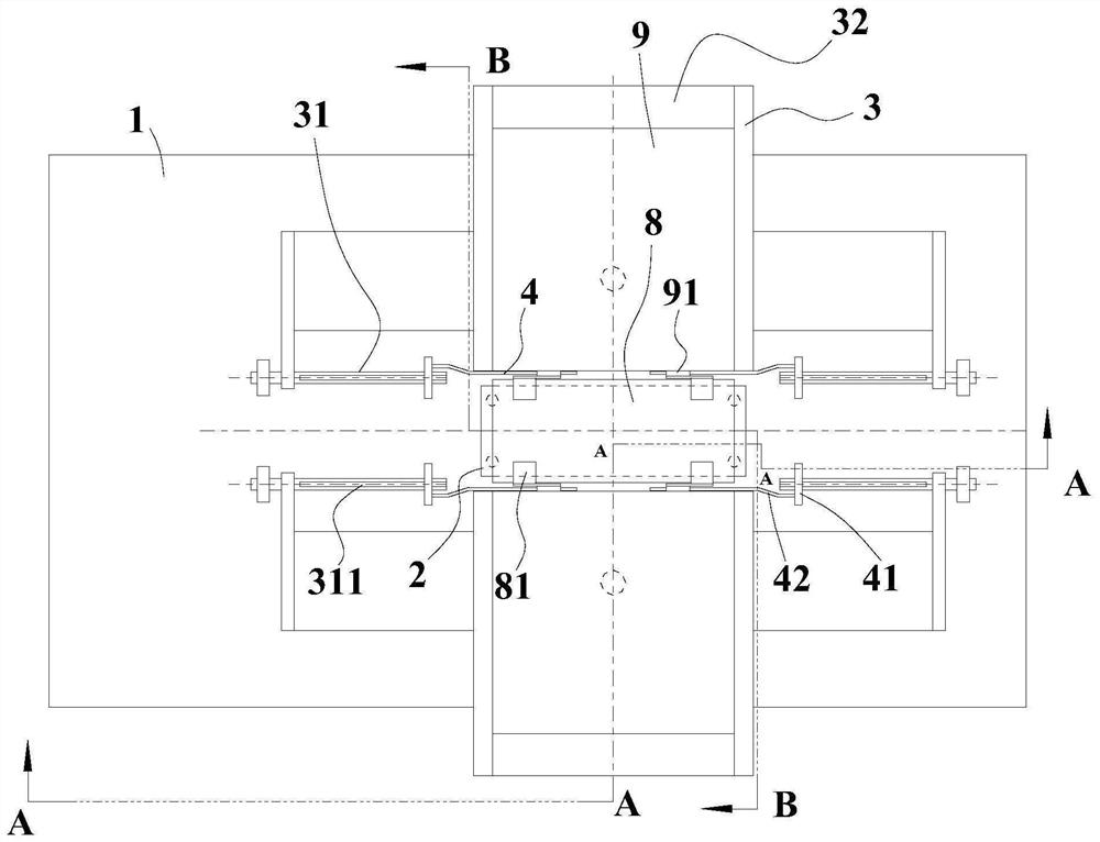
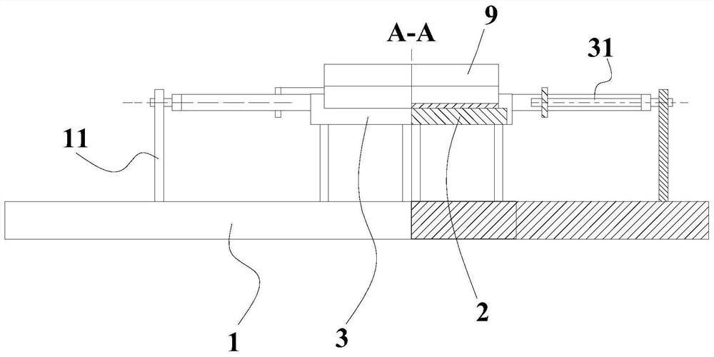
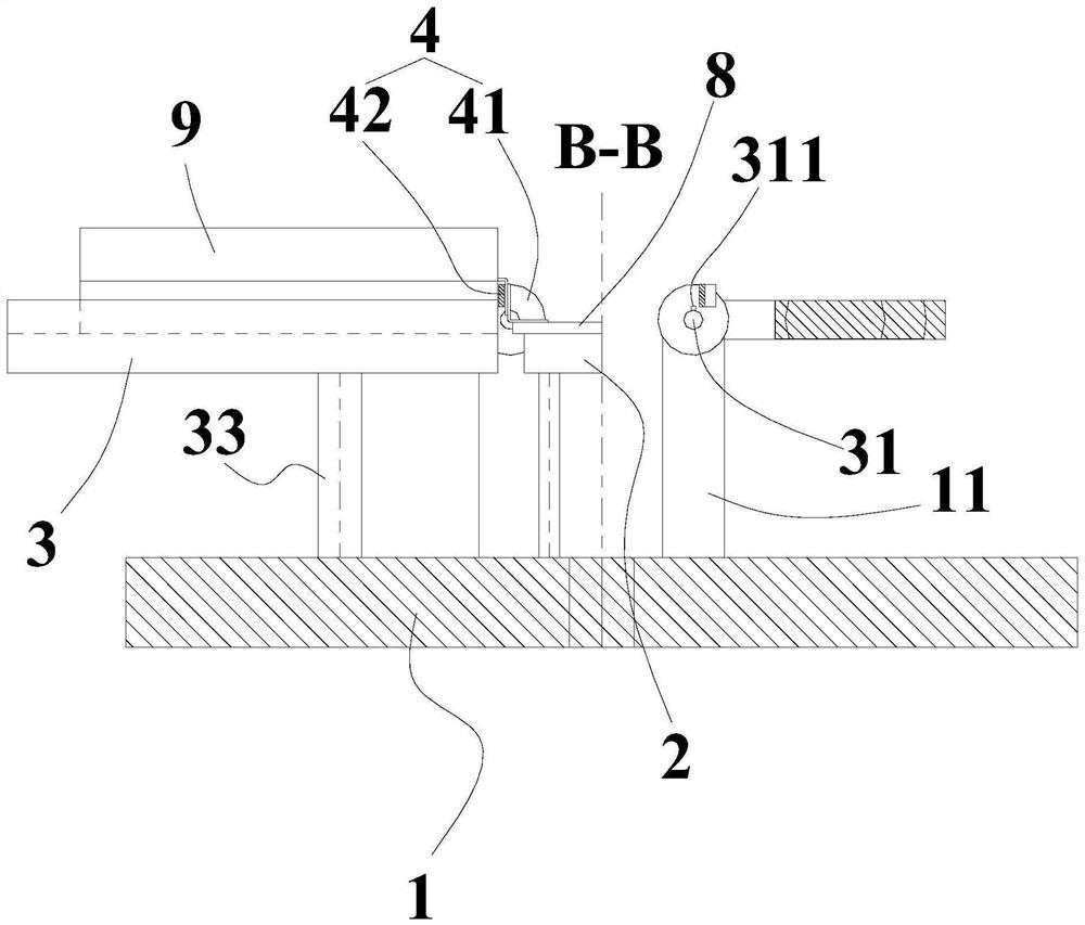
[0059] Such as figure 1 As shown, an off-line assembly device for a multi-roll core lithium battery includes a bracket 1 , a cover support plate 2 , a composite core plate 3 , and a folding knife 4 .

[0060] In this embodiment, the main function of the bracket 1 is to provide installation positions for the rest of the components. The bracket 1 is not limited to a specific shape, as long as it can meet the requirements of installing and matching the various components, and realize the corresponding functions. The bracket 1 in the embodiment is a rectangular plate.

[0061] For ease of description and understanding, the figure 1 The angle of view is the angle of view of the top view, and the rest of the orientations are based on this. It should be understood that this orientation setting is only for the convenience of description and understanding, and should not be construed as a limitation of the present invention.

[0062] Such as figure 1 , 3 As shown, a cover plate sup...

Embodiment 2

[0074] The difference between this embodiment and Embodiment 1 is:

[0075] Such as Figure 4 As shown, it also includes a shifting block 5 slidably installed on the bracket 1, and the sliding direction of the shifting block 5 is parallel to the sliding direction of the sliding block 41; that is, the sliding direction of the shifting block 5 is along the left and right directions.

[0076] Such as Figure 4 As shown, the shift block 5 is provided with a shift fork 51 with an opening facing the slider 41 , and the slider 41 is located in the opening of the shift fork 51 ; the bracket 1 is provided with a shift block driving mechanism 6 .

[0077] Such as Figure 4 , 5 As shown, two shifting blocks 5 are provided, and the two shifting blocks 5 are respectively located between the rotating shafts 31 at the same end of the two composite core boards 3. Specifically, two pairs of shafts along the left and right sides are arranged between the rotating shafts 31 on the front and re...

Embodiment 3

[0082] The difference between this embodiment and embodiment two is:

[0083] Such as Figure 7-9 As shown, the rotating shaft 31 is provided with the same gear 312 , and the corresponding gears 312 of the two core plates 3 mesh with each other.


PUM


Abstract

The invention relates to the field of battery assembly, in particular to an off-line assembling device for a multi-roll-core lithium battery. The off-line assembling device comprises a support, wherein a cover plate supporting plate is horizontally arranged on the support; the two sides of the cover plate supporting plate are each provided with a core combining plate, rotating shafts are fixedly arranged on the core combining plates, the rotating shafts are rotationally installed on the support and are horizontally arranged, and the rotating shafts on the two sides of the cover plate supporting plate are parallel; and a folding knife is mounted on each rotating shaft in a sliding manner, can slide to a position between the cover plate supporting plate and the core combining plate along the axial direction of the rotating shaft, and can rotate along with the rotating shaft. The off-line assembling device for the multi-roll-core lithium battery has the advantages that when the off-line assembling device is adopted for battery assembling, operation is convenient; and the off-line assembling device has the advantages of being simple in structure, high in precision, low in cost, convenient to use and the like.

Description

technical field [0001] The invention relates to the field of battery assembly, in particular to an off-line assembly device for a multi-roll core lithium battery. Background technique [0002] The lithium battery assembly process is one of the key processes in the lithium battery manufacturing process. This process forms the battery by combining the formed winding core with the core, inserting the shell and welding. When the core is combined, it is usually realized by a core-combining device. For example, the Chinese utility model patent with the publication number CN208368654U discloses a core-combining device for a lithium battery, which includes: a bottom plate, a core-combining component and a gland component; the core-combining component includes a column and two core-combining rods; the column is installed on the bottom plate, and the two core-combining rods are rotated and installed on the column and arranged symmetrically, and the middle part of the core-combining ro...

Claims


Application Information

Patent Timeline
Patent Type & Authority Applications(China)
IPC IPC(8): H01M10/0587B21D39/00B21D43/00B23P19/00
CPCH01M10/0587B23P19/00B21D39/00B21D43/003Y02P70/50Y02E60/10
Inventor 王友路
Owner HEFEI GUOXUAN HIGH TECH POWER ENERGY
Learn More