Landscaping pruning device
A pruning device and landscaping technology, applied in the field of landscaping, can solve the problems of not being able to adjust the angle of the curved plate freely, and cannot meet the pruning requirements, and achieve the effect of improving convenience
- Summary
- Abstract
- Description
- Claims
- Application Information
AI Technical Summary
Problems solved by technology
Method used
Image

Examples
Embodiment 1
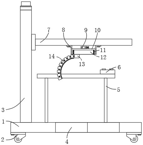
[0031] Depend on figure 1 , figure 2 , image 3 , Figure 5 and Figure 6 Given, the present invention provides the following technical solutions: a landscaping pruning device, including a base 1, front wheels 2 and rear wheels 32 are symmetrically installed at both ends of the bottom of the base 1, and a groove is provided at the center of one side of the base 1 4. A handle bar 5 is installed on the top side of the base 1, a control board 6 is installed on the handle bar 5, a PLC controller 36 is installed inside the control board 6, and a mounting plate 7 is fixed on the top of the base 1 through the height adjustment component 3 , the bottom of the mounting plate 7 is fixed with a rotating base 10 through a bracket 8, the inner rotation of the rotating base 10 is connected with a turntable 12, the top center of the rotating base 10 is equipped with a first reduction motor 9 for driving the turntable 12, and the bottom of the turntable 12 is A connecting seat 13 is inst...
Embodiment 2
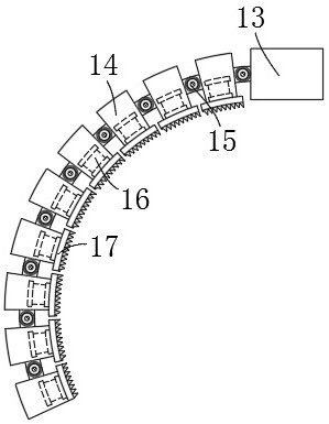
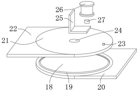
[0038] In Embodiment 1, the rotation angle of the dynamic joint disc 18 cannot be accurately monitored, refer to image 3 , as another preferred embodiment, the difference from Embodiment 1 is that an angle sensor 27 is installed on the output shaft of the stepper motor 26, the angle sensor 27 is electrically connected to the input end of the PLC controller 36, and the output of the PLC controller 36 The terminal is electrically connected to the stepping motor 26, and the angle sensor 27 provided can accurately monitor the rotation angle of the moving joint plate 18 driven by the stepping motor 26, so as to facilitate the adjustment of different angles of the arc-shaped plate to meet different usage requirements.
Embodiment 3
[0040] It is inconvenient to adjust the height of the curved plate in Embodiment 1, refer to Figure 4 , as another preferred embodiment, the difference from Embodiment 1 is that the height adjustment assembly 3 includes a slide rail 28, a reciprocating screw 29, a slider 30 and a second reduction motor 31;
[0041] Slide rail 28 is fixed on the top of base 1, and the inside of slide rail 28 is connected with reciprocating screw mandrel 29, and the top of slide rail 28 is equipped with the second deceleration motor 31 that drives reciprocating screw mandrel 29, and the reciprocating screw mandrel 29 is meshed and connected with The slide block 30 that slides inside the slide rail 28, the slide block 30 is equipped with a mounting plate 7, works through the second reduction motor 31 provided, and drives the reciprocating screw rod 29 to rotate inside the slide rail 28, thereby driving the slide block 30 in the slide rail 28. The internal movement of the slide rail 28 facilitate...
PUM
 Abstract
Description
Claims
Application Information